EasyManuals Logo

Mindray DC-70 Service Manual

Mindray DC-70
295 pages
To Next Page IconTo Next Page
To Previous Page IconTo Previous Page
Page #198 background imageLoading...
Page #198 background image
10-8 Optional Installation/Assembly
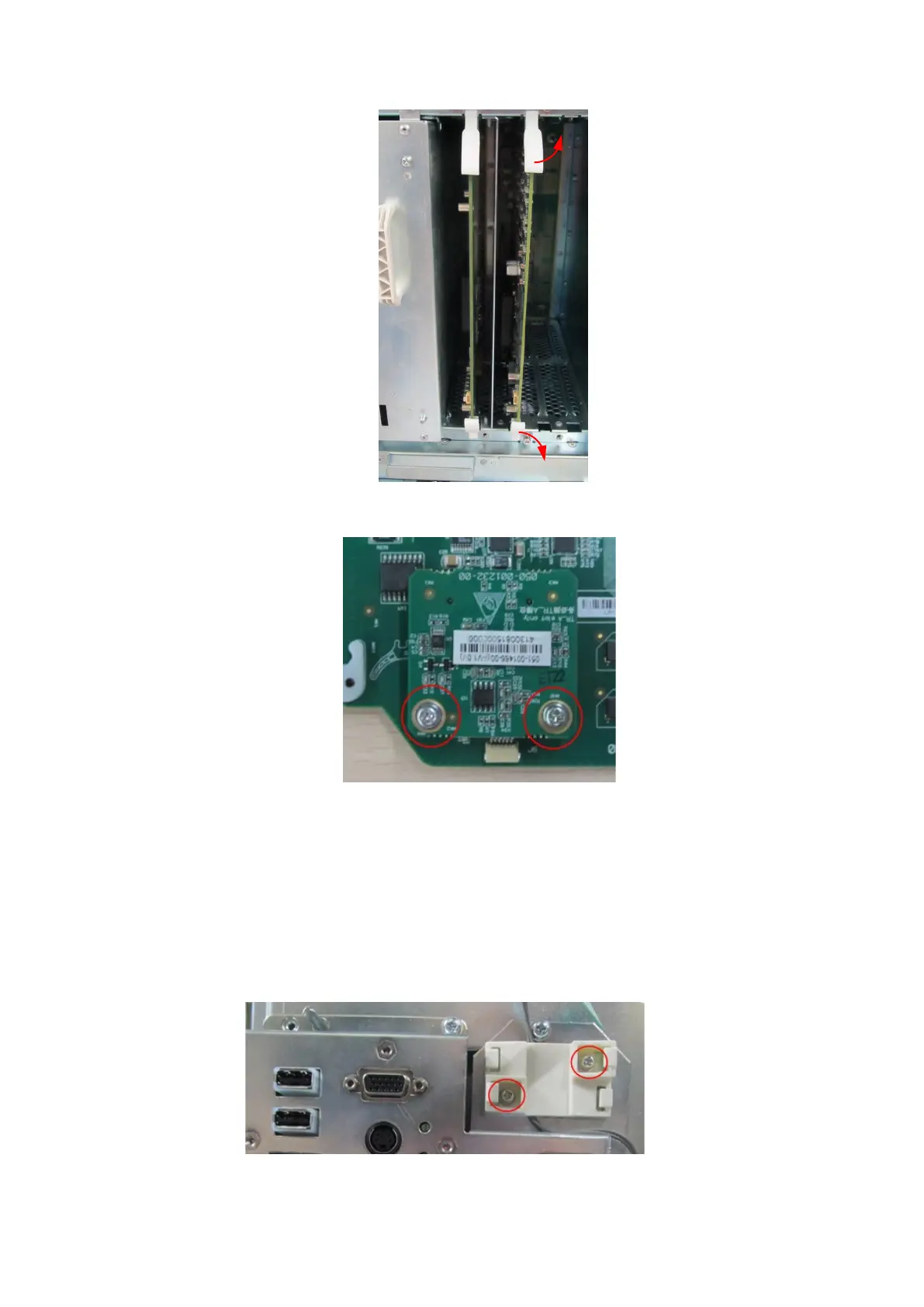
3. Fix CW board to TR board in socket A with two M3 X 8 screws.
4. Insert TR board into corresponding slot. Fix the plastic clips. Assemble the left side panel. Then,
the installation is completed.
10.2.4 The Assembly of Wireless Network Adaptor
The disassembly tool: cross-headed screwdriver (M3, M4), anti-electrostatic glove
1. Remove the left/right side panels and the rear cover (refer to chapter 9.3.2).
2. Fix the cable bracket to the device with two M3 X 8 screws.
3. Insert WIFI board into the cable bracket.

Table of Contents

Questions and Answers:

Question and Answer IconNeed help?

Do you have a question about the Mindray DC-70 and is the answer not in the manual?

Mindray DC-70 Specifications

General IconGeneral
Power Supply100-240V AC, 50/60Hz
Imaging ModesB-mode, M-mode, Color Doppler, Power Doppler, Pulsed Wave Doppler, Continuous Wave Doppler
ProbesConvex, Linear, Phased Array, Volume
ConnectivityUSB, Ethernet, VGA
Advanced Features3D/4D Imaging
ApplicationsAbdominal, Obstetrics, Gynecology, Cardiac, Small Parts, Vascular, Musculoskeletal, Urology
WeightApprox. 85 kg
Operating SystemWindows-based

Related product manuals