EasyManuals Logo

Mindray DC-70 Service Manual

Mindray DC-70
295 pages
To Next Page IconTo Next Page
To Previous Page IconTo Previous Page
Page #200 background imageLoading...
Page #200 background image
10-10 Optional Installation/Assembly
7. The installation is completed after the right/left side panels and the rear cover are assembled.
10.2.5 4D Assembly
The disassembly tool: cross-headed screwdriver (M3, M4), anti-electrostatic glove
1. Remove the left side panels (refer to chapter 9.3.2 step 1).
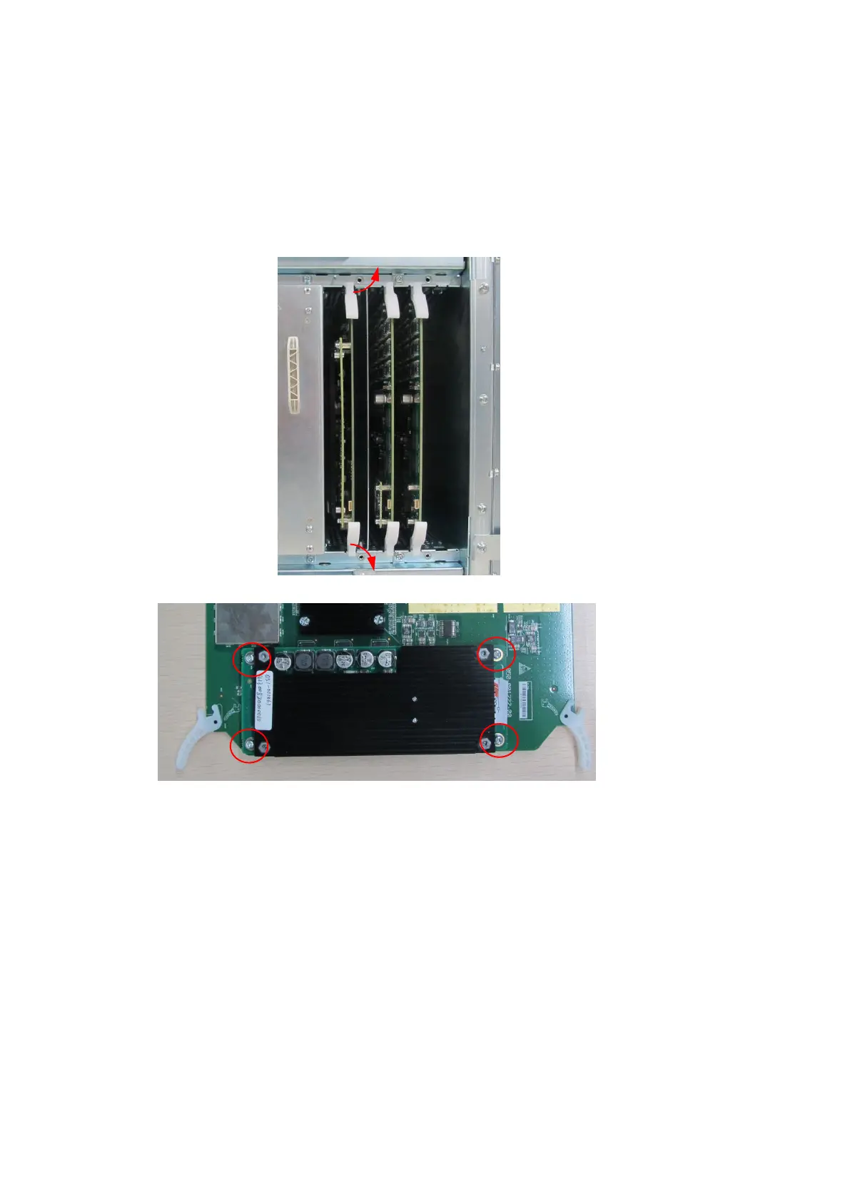
2. And remove engine board.
3. Fix 4D assembly to corresponding positions on engine board with four M3 X 8 screws.
4. Insert engine board into corresponding slot. Fix the plastic clips. Assemble the left side panel.
Then, the installation is completed.

Table of Contents

Questions and Answers:

Question and Answer IconNeed help?

Do you have a question about the Mindray DC-70 and is the answer not in the manual?

Mindray DC-70 Specifications

General IconGeneral
Power Supply100-240V AC, 50/60Hz
Imaging ModesB-mode, M-mode, Color Doppler, Power Doppler, Pulsed Wave Doppler, Continuous Wave Doppler
ProbesConvex, Linear, Phased Array, Volume
ConnectivityUSB, Ethernet, VGA
Advanced Features3D/4D Imaging
ApplicationsAbdominal, Obstetrics, Gynecology, Cardiac, Small Parts, Vascular, Musculoskeletal, Urology
WeightApprox. 85 kg
Operating SystemWindows-based

Related product manuals