Image Optimization 5-37
5.11 3D Imaging
3D imaging is largely environment-dependent, so the images obtained are provided for
reference only, not for confirming diagnoses.
5.11.1 Overview
Ultrasound data based on three-dimensional imaging methods can be used to image any structure
where a view cannot be achieved with the standard 2D-mode and to improve the understanding of
complex structures.
Terms
3D image Volume Rendering (VR): the image displayed to represent the volume data.
View point: a position for viewing volume data/3D image.
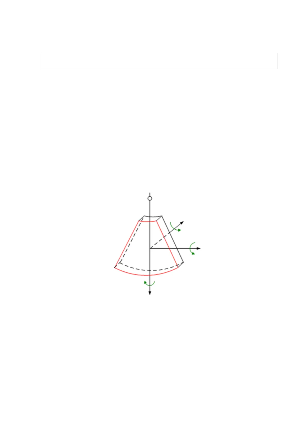
MultiPlaner Rendering (MPR): the three sectional planes of the volume acquisition. As
shown in the figure below, the XY-paralleled plane is the C-section, the XZ-paralleled
plane is the B-section, and the YZ-paralleled plane is the A-section. The probe is moved
along the X-axis.
ROI (Region of Interest): a volume box used to determine the height and width of scanning
volume.
VOI (Volume of Interest): a volume box used to display the 3D image (VR) by adjusting the
region of interest in MPR.
ROI and VOI
After the system enters 3D imaging, a B image with ROI displays on the screen. A line (shown
in the following figure) shows that the upper edge position of the VOI is inside the ROI.