V Series Operating Instructions 9 - 17
ECG – Arrhythmia Preparation and Lead Placement
9.5.3.6 Lead Placement: Modified Chest Lead (MCL) Monitoring
• The recommended lead placement for MCL monitoring is as follows.
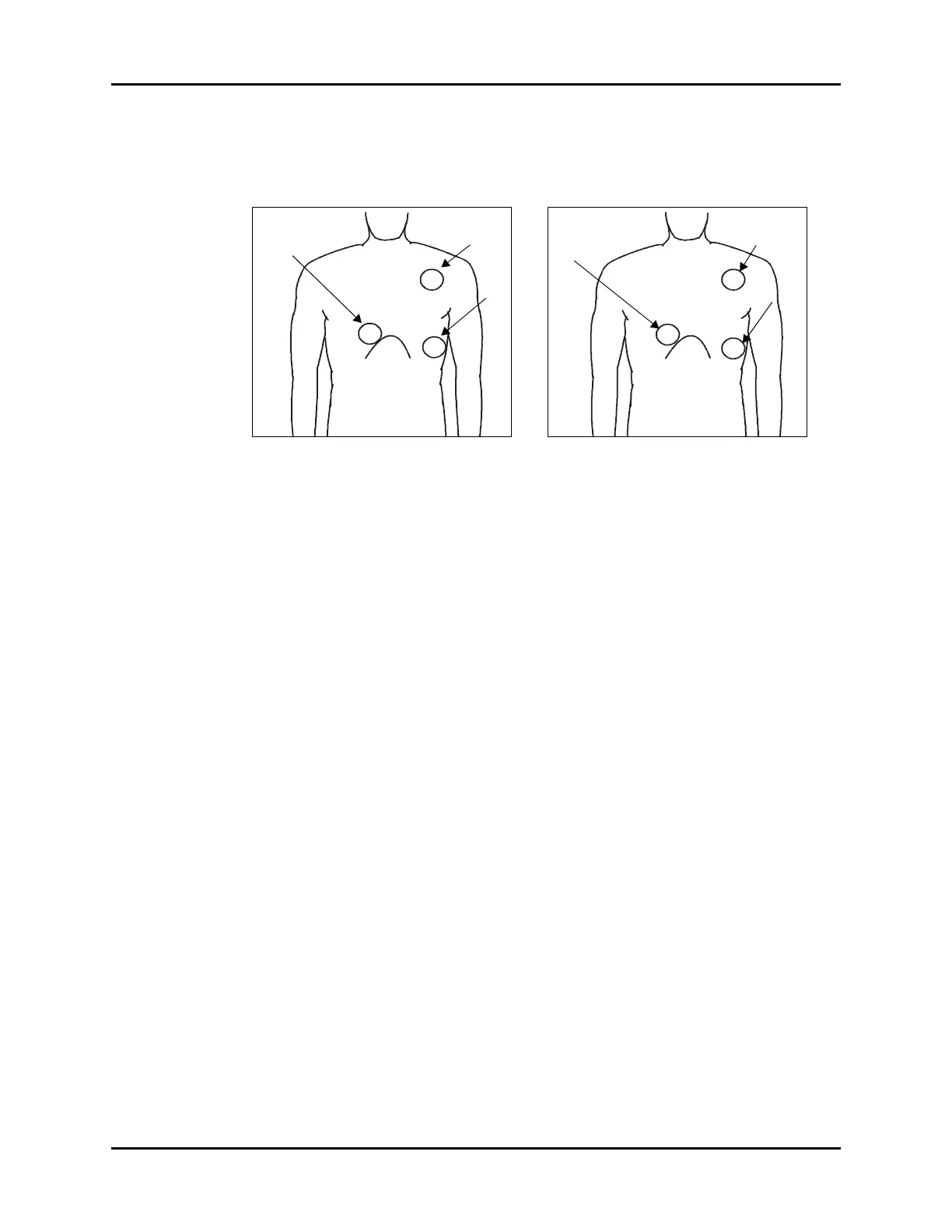
FIGURE 9-13 MCL Monitoring with a
3-wire Lead Set (AHA)
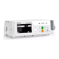
FIGURE 9-14 MCL Monitoring with a
3-wire Lead Set (IEC)
• Place the RA (white) electrode under the
patient’s left clavicle, at the mid-clavicular
line within the rib cage frame.
• Place the LA (black) electrode on the right
sternal border, at the fourth intercostal
space within the rib cage frame.
• Place the LL (red) electrode on the patient’s
lower left abdomen within the rib cage
frame.
• Select ECG Lead I for MCL
1
monitoring.
Lead I is the direct electrical line between
the RA (white) electrode and the LA (black)
electrode.
• Select ECG Lead II for MCL
6
monitoring.
Lead II is the direct electrical line between
the RA (white) electrode and the LL (red)
electrode.
• Place the R (red) electrode under the
patient’s left clavicle, at the mid-clavicular
line within the rib cage frame.
• Place the L (yellow) electrode on the right
sternal border, at the fourth intercostal
space within the rib cage frame.
• Place the F (green) electrode on the
patient’s lower left abdomen within the rib
cage frame.
• Select ECG Lead I for MCL
1
monitoring.
Lead I is the direct electrical line between
the R (red) electrode and the L (yellow)
electrode.
• Select ECG Lead II for MCL
6
monitoring.
Lead II is the direct electrical line between
the L (red) electrode and the F (green)
electrode.