Services Units and Gateways
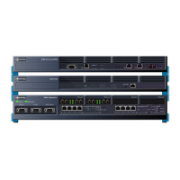
SX-200 Bay
Description
The SX-200 Bay cabinet holds up to 12 card slots: eight slots support line (ONS, OPS or DNI)
cards, and four support the control cards and the FIM or CIM carrier cards. Up to seven bays
can be connected to a 3300 ICP using FIM or CIM cables.
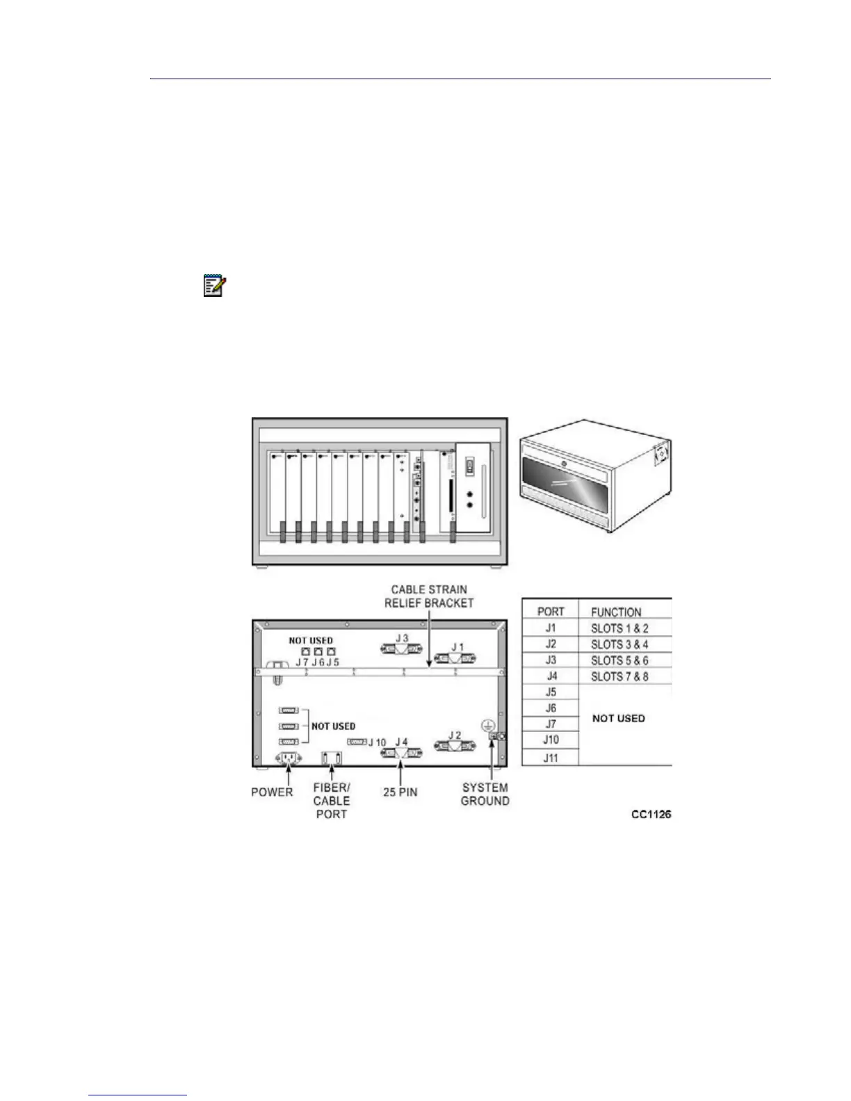
Located on the rear of the SX-200 Bay cabinet are four 25-pin connectors (J1- J4 for the
peripheral interface cards), three RJ-45 connectors (J5 and J6 for T1 trunks and J7 for a system
fail transfer control port), a printer port, a grounding connector, a maintenance port, and two
RS-232 connectors (J10 and J11 for the PRI maintenance).
The Bay cabinet consists of the following components:
• Peripheral Interface Cards: The peripheral interface cards connect peripheral devices
(such as SUPERSET™ telephones) to the system. They are located in slots 1 through 8.
• Bay Power Supply (AC): The power supply converts AC input power to the voltages
required by the circuit cards and FIMs (+5 Vdc, +12 Vdc, -27 Vdc, -48 Vdc and 80 Vac
Note: SX-200 Bays are supported by MXe controllers only.
Figure 33: SX-200 Bay
 Loading...