Hardware Technical Reference Manual
DIP Switch Settings
Universal and R2 NSU DIP Switch Settings
BRI NSU DIP Switch Settings
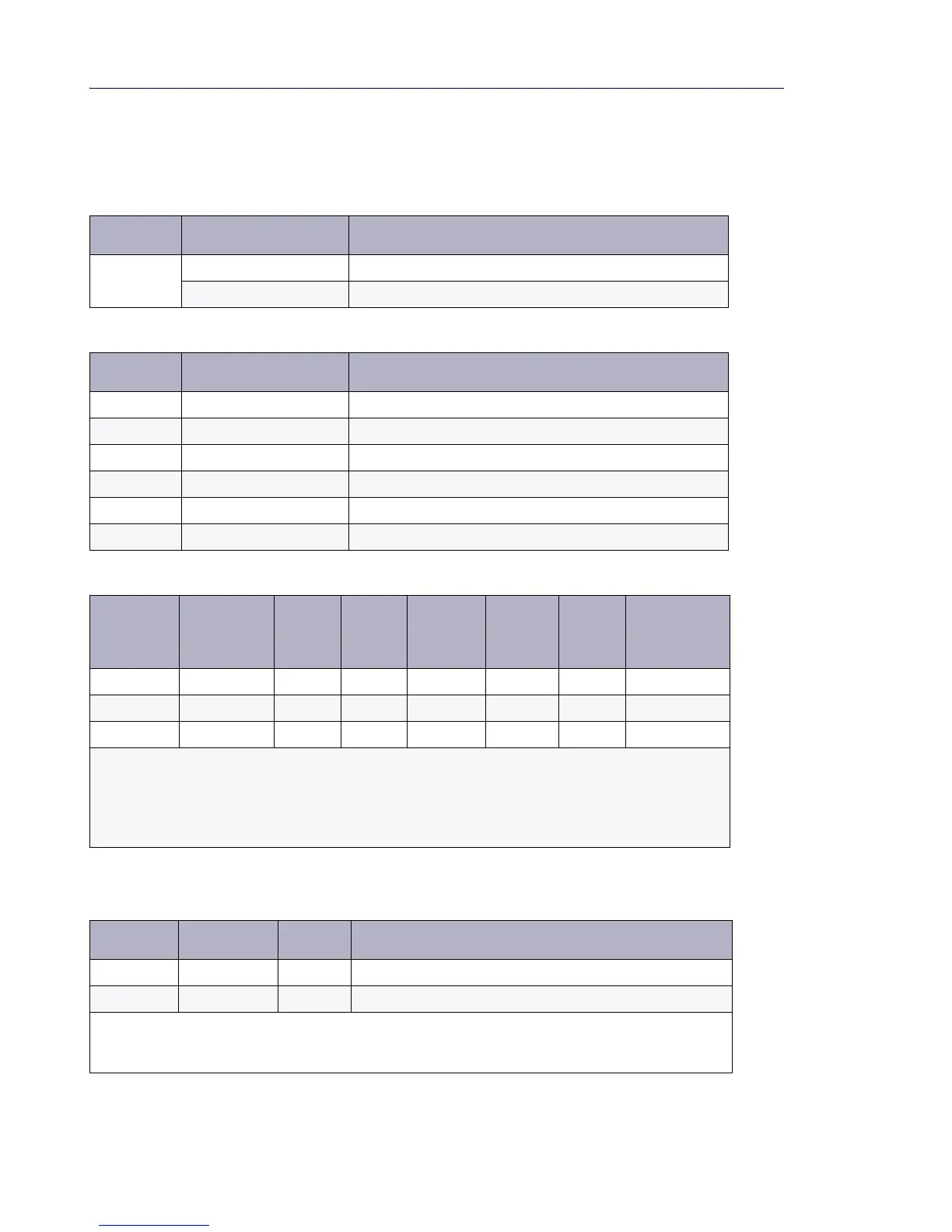
Table 39: Message Link DIP Switch Settings
DIP Switch Use Notes
Rear panel,
left side
Primary NSU Set to 1 (up). Connected to the controller.
Secondary NSU Set to 2 (down). Connected to another NSU.
Table 40: T1/E1 Ports DIP Switches Defined
DIP Switch Use Notes
1 Tx Ground Ground when down; floating when up.
2 Rx Ground Ground when down; floating when up.
3 Impedance selector #1 120 ohm (enabled when down)
4 Impedance selector #2 100 ohm (enabled when down)
5 Impedance selector #3 75 ohm (enabled when down)
6 LT/NT selector Up for NT; down for LT.
Table 41: T1/E1 Ports DIP Switch Settings
Impedance Trunk Mode
1
Tx Gnd
2
Rx Gnd
3
120 ohm
4
100 ohm
5
75 ohm
6
LT/NT
(Note 2)
100 T1 (T1/D4) Up Up Up Down Up Up/Down
120 E1 (PRI) Up Up Down Up Up Up/Down
75 E1 (R2) Note 1 Note 1 Up Up Down Up/Down
Note 1: The Ground setting is site-dependent. Normally, Tx is grounded and Rx is not grounded, but
that depends on which remote connection is grounded. These switches are used only with the coaxial
adapter (BNC adapter required); leave up (floating) for twisted pair connection to the E1 port.
Note 2: See Table 46 on page 74 for T1 and E1 Connector Pin Allocation for setting dip switch 6,
LT/NT.
Table 42: CEPT Mode - E1 Port DIP Switch Settings
DIP Switch Use Default Notes
1 Tx Ground Up Ground when down; floating when up.
2 Rx Ground Up Ground when down; floating when up.
Note: This setting is site-dependent. Normally Tx is grounded and Rx is not grounded, but that depends
on which remote connection is grounded. These switches are used only with the coaxial adapter; leave
up (floating) with twisted pair connection. Not required for RJ-45 connector.