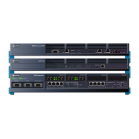
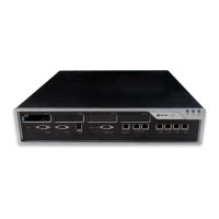
Services Units and Gateways
CIM Port
The CIM ports require standard 8-pin modular jacks (RJ-45) consisting of 2 balanced signal
pairs on a Category 5 Universal Twisted Pair (UTP) crossover cable. The twisted pairs are
arranged as: 1,2: 3,6; 4,5; 7,8. Each tied pair is connected to a 75 ohm resistor. The following
table lists the signal for each pin.
ASU II ONS Parameters
The ASU II ONS parameters are the same as those for the Analog Boards; please refer to
Table 18, “ONS Circuit Impedance Values,” on page 49.
ASU and Universal ASU ONS Parameters
ONS Transmission Parameters
16 ONS Tip 16 ONS Tip 16 41 ONS Ring 16 ONS Ring 16
17 LS Tip 1 ONS Tip 17 42 LS Ring 1 ONS Ring 17
18 LS Tip 1-1 ONS Tip 18 43 LS Ring 1-1 ONS Ring 18
19 LS Tip 2 ONS Tip 19 44 LS Ring 2 ONS Ring 19
20 LS Tip 1-2 ONS Tip 20 45 LS Ring 1-2 ONS Ring 20
21 LS Tip 3 ONS Tip 21 46 LS Ring 3 ONS Ring 21
22 LS Tip 1-3 ONS Tip 22 47 LS Ring 1-3 ONS Ring 22
23 LS Tip 4 ONS Tip 23 48 LS Ring 4 ONS Ring 23
24 LS Tip 1-4 ONS Tip 24 49 LS Ring 1-4 ONS Ring 24
25 N/C N/C 50 N/C N/C
Table 58: CIM Port Pin Allocation
Pin Number Signal Pin Number Signal
1RX+5 –
2 RX- 6 TX-
3TX+7 –
4 – 8 –
Table 59: Transmission Parameters
ASU variant Input Impedance Balance Impedance
NA 600 ohms 600 ohms
UK
1
300R+(1000R||220nF) 300R+(1000R||220nF)
Table 57: 25-pair Connector Pin Allocation (continued)
Pin Number
Signal
Pin Number
Signal
Universal ASU ASU Universal ASU ASU