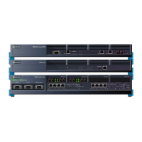
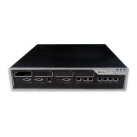
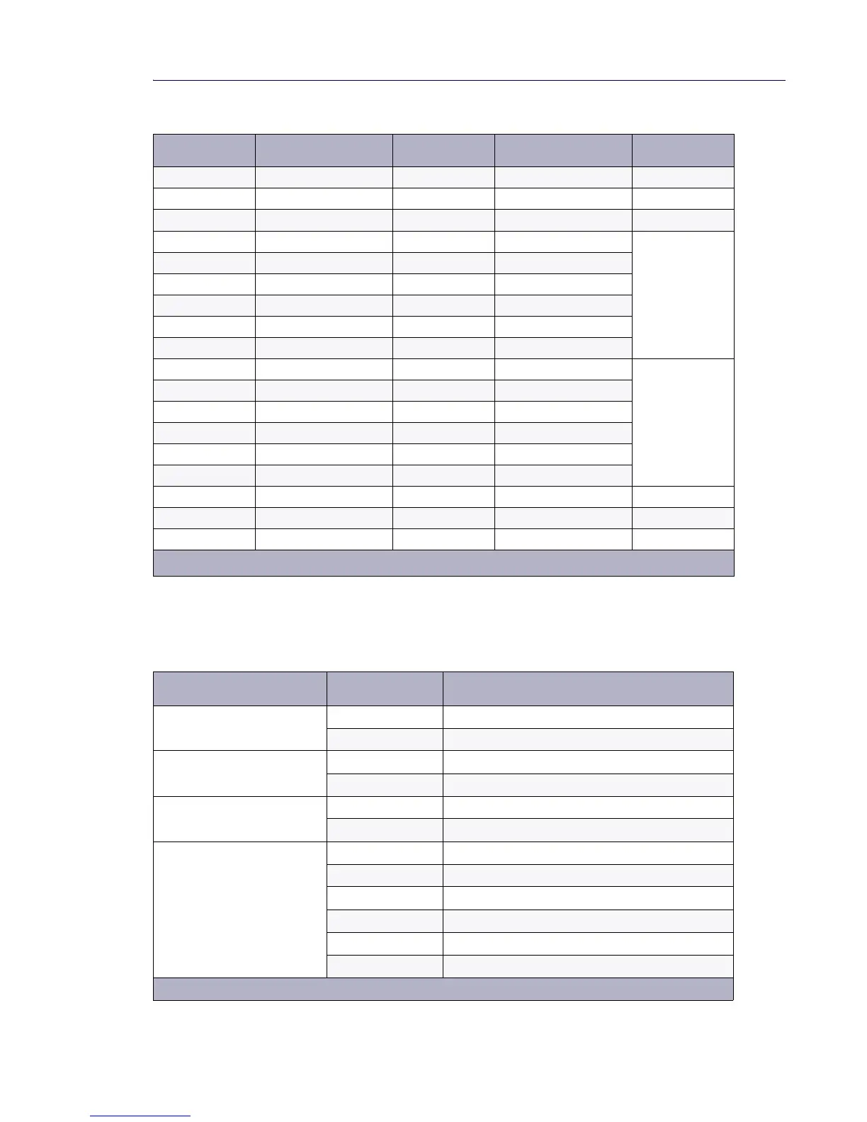
CX/CXi and MXe Line and Trunk Connector
8 – 33 – –
9–34––
10 – 35 – –
11 PFT_TK_ T1 36 PFT_TK_ R1 Main
12 PFT_TK_ T2 37 PFT_TK_ R2
13 TK_TIP3 38 TK_RING3
14 TK_TIP4 39 TK_RING4
15 TK_TIP5 40 TK_RING5
16 TK_TIP6 41 TK_RING6
17 TK_TIP7 42 TK_RING7 Option
18 TK_TIP8 43 TK_RING8
19 TK_TIP9 44 TK_RING9
20 TK_TIP10 45 TK_RING10
21 TK_TIP11 46 TK_RING11
22 TK_TIP12 47 TK_RING12
23 – 48 – –
24 – 49 – –
25 – 50 – –
Table 36: RJ-11 Line/Trunk Connector Pin Allocation
Port Pin Number Function
LS 1 - 6 3 Ring
4 Tip
ONS 1 - 4 3 Ring
4 Tip
ONS 3 - 4 2 Contact sensor
5 Contact sensor
Relay 1/2
(not used)
3 RLY1_Common
4 RLY1_NO (normally open)
6 RLY1_NC (normally closed)
2 RLY2_Common
5 RLY2_NO (normally open)
1 RLY2_NC (normally closed)
Page 1 of 2
Table 35: Amphenol Line/Trunk Connector Pin Allocation (continued)
Pin Number Signal Pin Number Signal Board
Page 2 of 2