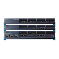
Services Units and Gateways
Paging (Universal ASU only)
The paging interface provides two paging ports.
Each paging port is a transformer-coupled interface providing:
• 600 ohm input impedance
• Full duplex capability
• A complete 2/4 wire hybrid interface
• A balance impedance set at 600 ohms.
The two overhead paging outputs, in combination with their relay contacts, support two paging
zones.
Paging is accomplished by one of two methods:
• Zone control via outpulsed DTMF digits
• E&M trunk emulation using contact-closure control.
The Paging Connector Pin Allocation is shown in the following table.
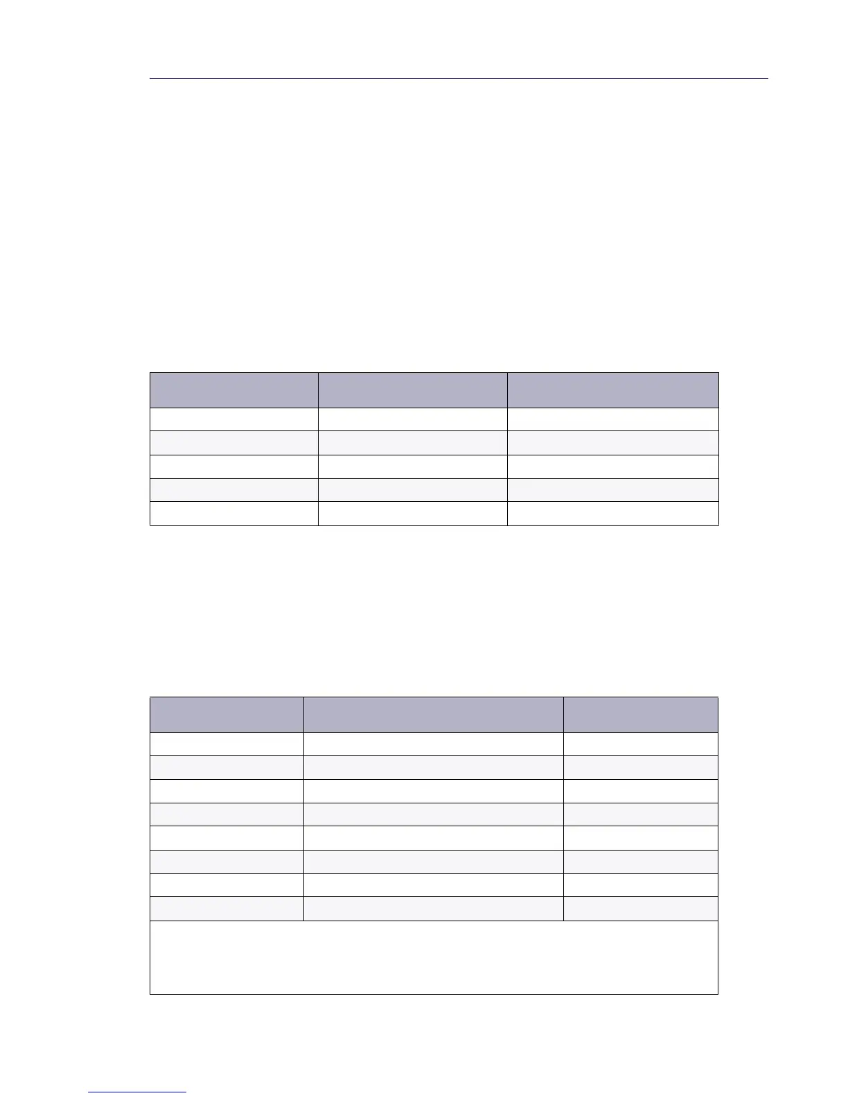
Table 50: ASU Paging Zones vs. Audio Circuit Numbers and Relay Positions
ASU Paging Zone Number Paging Audio Circuit Number Paging Circuit’s Relay Position
11 Off
2 1 On
32 Off
4 2 On
0 1 & 2 Off & Off
Table 51: Paging Connector Pin Allocation
Pin Signal Zone
1Tip00
2 Ring 00
3 Common contact 00
4 Tip 01
5 Ring 01
6 Normally open contact 00
7 Common contact 01
8 Normally open contact 01
Note: The Paging port is a standard 8-pin modular RJ-45 connector located on the rear panel of the
Universal ASU.
Note: Each paging port has a tip/ring pair for audio and a second tip/ring pair contact closures for zone
control. The contact closes when paging on zones.