414
26 BASIC CONCEPT
26.7 Determination of Control System/Standby System
■I/O signals
The following table lists the details on the I/O signals.
■Setting time of the external on delay timer
For the on delay timer for starting up the control system, set the setting time longer than the time duration of the start-up of
both systems.
*1
The following shows a reference setting time.
• Setting time of the external on delay timer = Start-up time of the CPU module + Time lag of power-on +
Check the start-up time with the actual system and adjust the setting time () because the start-up time of the CPU module
depends on the system configuration.
*1 If the setting time of the external on delay timer is shorter than the above, a stop error may occur on one system even though tracking
cables are connected properly because turning on X20 (Control System Start-up Setting (Input (X))) starts this program example.
Parameter settings
The following shows parameter settings.
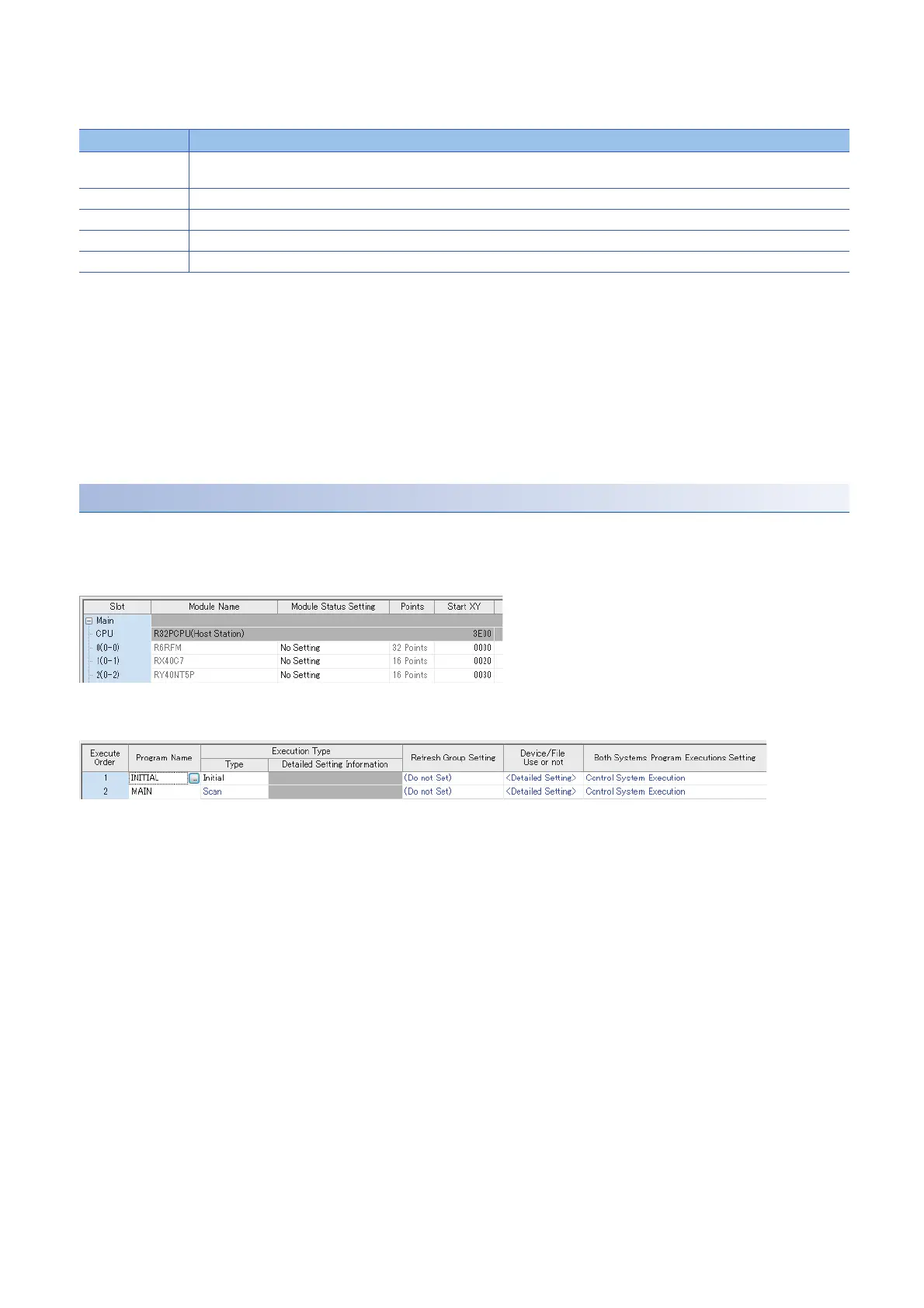
■System parameter
Set the system parameter according to the system configuration in "I/O Assignment Setting".
■CPU parameter (program settings)
Set this program example (INITIAL in this example) in "Program Setting" as follows.
Device No. Signal name
X20 Control System Start-up Setting (Input (X))
With the on delay timer wired externally, X20 turns on and the CPU module starts as the control system after a certain time.
X21 Starting up (other system)
X22 Control system (other system)
Y31 Starting up (own system)
Y32 Control system (own system)
• Set "INITIAL" for "Execution Type".
• Set "Control System Execution" in "Both Systems Program Executions Setting".

 Loading...

