27 PROCEDURE FOR STARTING UP A REDUNDANT SYSTEM
27.1 Overview
423
27
7. Setting parameters
Set system parameters, CPU parameters, and module parameters. ( MELSEC iQ-R CPU Module User's Manual
(Startup))
• To use the functions that require an SD memory card, set memory card parameters.
• To mount an intelligent function module, set intelligent function module parameters.
Users can set system parameters by reading the actual system configuration to the module configuration of
the engineering tool.
8. Creating a program
Create a program with the engineering tool. After creating the program, convert the program and save the project. (
MELSEC iQ-R CPU Module User's Manual (Startup))
9. Writing the system A/B setting
Set the system A or B with the engineering tool. ( Page 431 System A/B Settings)
10. Writing data to the programmable controller
Write the set parameters and created programs to both systems with the engineering tool. ( Page 433 Writing Data to the
Programmable Controller)
11. Resetting the CPU modules
Restart both systems with either of the following methods.
• Powering on the systems
• Resetting the CPU modules
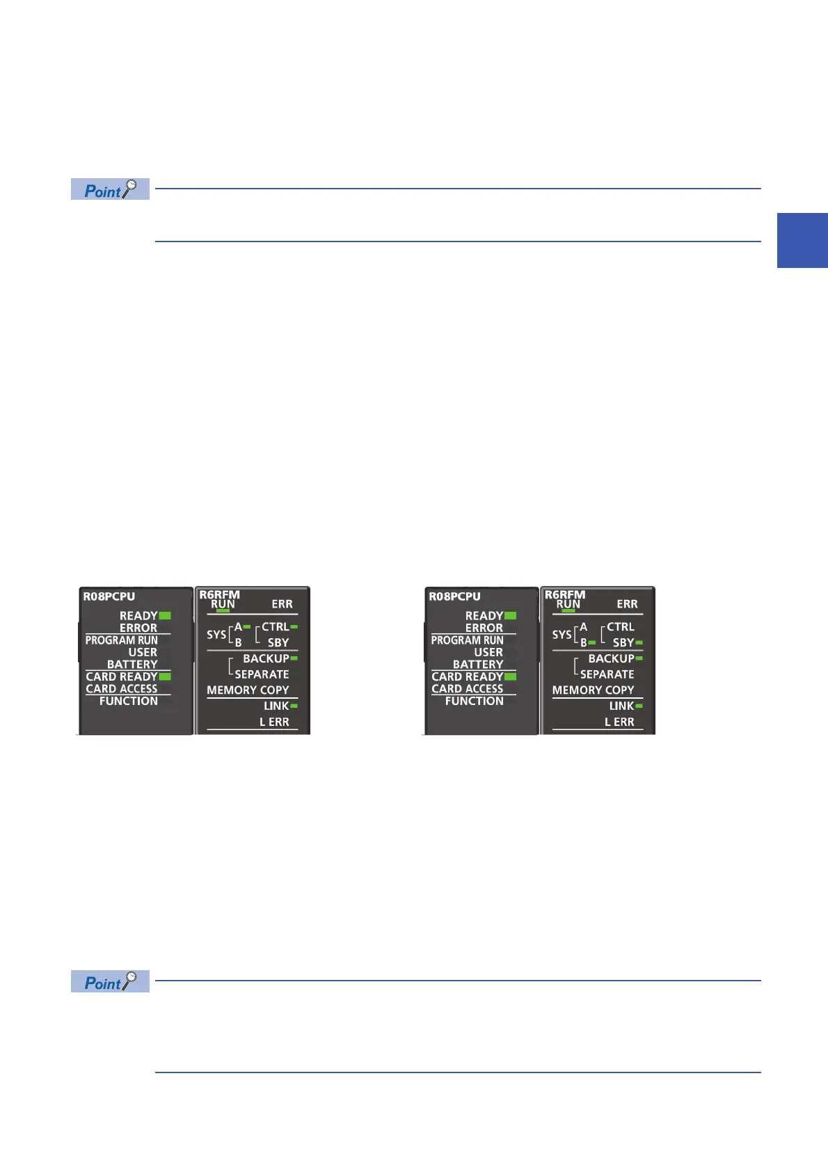
12. Checking the LEDs
Check that the LEDs of each CPU module and redundant function module are in the following states. The CARD READY LED
status depends on whether an SD memory card has been installed to each CPU module or not.
When an error has occurred, the following LEDs are on. Check details of the error with the engineering tool and eliminate the
error cause.
• CPU module: ERROR LED ( MELSEC iQ-R CPU Module User's Manual (Startup))
• Redundant function module: ERR LED, L ERR LED ( Page 799 When an error has occurred in a redundant function
module)
To start up the system when the data logging function is used, refer to the following.
Page 427 Precautions on starting up the system when the data logging function is used
13. Running a program
Power off both systems. Set the RUN/STOP/RESET switch of the CPU module of each system to the RUN position and
power on both systems.
Check that the PROGRAM RUN LED of the CPU module of the control system turns on.
Individually setting the RUN/STOP/RESET switch of each CPU module to the RUN position with the CPU
module powered on causes a continuation error due to the operating status mismatch and the error is
detected in the standby system. Therefore, to start up both systems simultaneously, performing step 13 is
recommended.
• LEDs of System A • LEDs of System B

 Loading...

