2 Ro bot ar m
Options
2-29
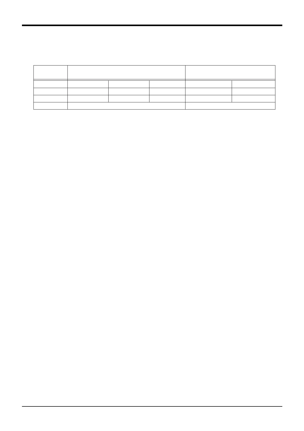
■ Cable configuration
The configuration of the flexible cable is shown in Table 2-12. Refer to this table when selecting the cable bare.
Table 2-12 : Cable configuration
Note) The square in the cable name indicates the cable length.
■ Fixing the flexible cable
(1) Connect the connector to the robot arm .
(2) Wind the silicon rubber around the cable at a position 300 to 400 mm from the side of robot arm and exten
-
sion section as shown in Fig. 2-13, and fix with the nylon clamp to protect the cable from external stress.
Item
Motor signal cable
1S- □□ LCBL(S)-01
Motor power cable
1S- □□ LCBL(P)-01
No. of cores
AWG#24(0.2mm
2
)-4P AWG#24(0.2mm
2
)-7P AWG#18(0.75mm
2
) AWG#16(1.25mm
2
)-4C AWG#18(0.75mm
2
)-4C
Finish dimensions Approx. φ6mm Approx. φ8.5mm Approx. φ1.7mm Approx. φ8.9mm Approx. φ6.5mm
No.of cables used 5 cables 1 cable 1 cable 2 cable 8 cable
No. in total 7 cables 10 cables

 Loading...


