3Controller
Options
3-73
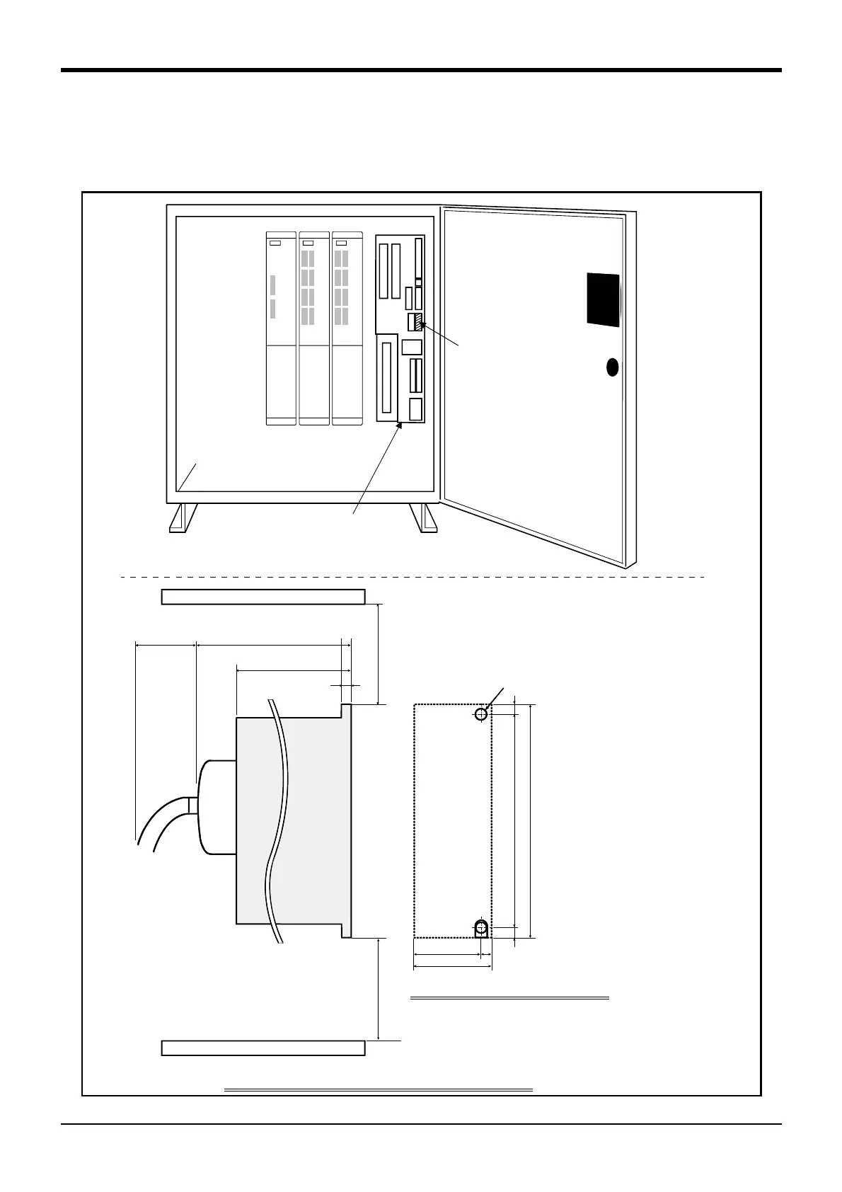
■ Installation method
The expansion parallel input/output unit is installed outside of the controller. Connect with the network connec
-
tion cable (NETcable-1) from the RIO1 connector in the into of the controller.(Terminator is connected at the
time of shipment)
Fig.3-26 : Installing the parallel input/output unit (CR3-535M controller)
Control panel installation dimensions
60
54 6
Radiation/wiring space
150
6
156
2-M5 screw
6
168
Heat radiation space
128
(175)
100
upside
Wiring
space
(40)
downside
<2A-RZ361>
<2A-RZ371>
Installation dimensions of 2A-RZ361/2A-RZ371
6
RIO1 connector
Control unit
(R6x2CPU)
The controller outside installation.

 Loading...


