4 - 19 4 - 19
MELSEC-
4 PROCEDURE UP TO DATA LINK
4.6.1 Connection of the CC-Link dedicated cables
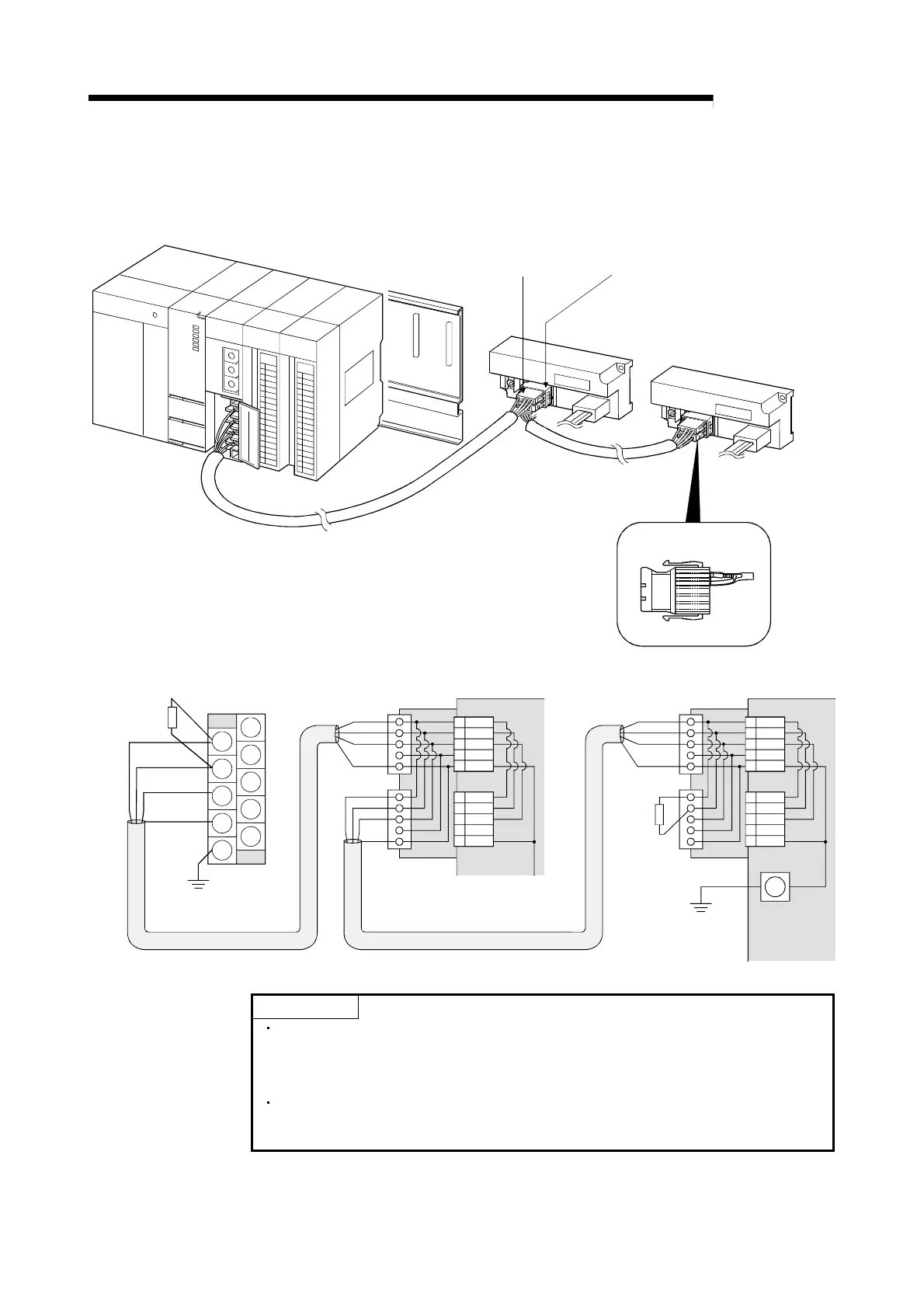
Connect the CC-Link dedicated cable between the AJ65SBT-CLB and master module
as shown below.
One-touch connector plug
for communication
Online connector for
communication
5432 1
5
4321
A6CON-TR11
One-touch connector plug
with terminating resistor
Terminating
resistor
(Blue)
(White)
(Yellow)
[CC-Link dedicated cable wiring diagram]
DA
DB
DG
SLD
FG
NC
NC
NC
NC
NC
Master module
(Blue)
(White)
(Yellow)
SLD
(Blue)
(White)
(Yellow)
SLD
1
2
3
4
5
1
2
3
4
5
Online connector
for communication
1
2
3
4
5
DA
DB
DG
NC
SLD
CONA
1
2
3
4
5
DA
DB
DG
NC
SLD
CONB
(Blue)
(White)
(Yellow)
SLD
1
2
3
4
5
1
2
3
4
5
1
2
3
4
5
DA
DB
DG
NC
SLD
CONA
1
2
3
4
5
DA
DB
DG
NC
SLD
CONB
Terminating
resistor
(A6CON-TR11)
FG
Ver.1.10 Compatible CC-Link dedicated cable (FANC-110SBH,CS-110,FA-CBL200PSBH)
Online connector
for communication
POINT
For this module, use the Ver. 1.10-compatible CC-Link dedicated cable (FANC-
110SBH,CS-110,FA-CBL200PSBH).You cannot use the Ver. 1.10-compatible
CC-Link dedicated cables, CC-Link dedicated cables or CC-Link dedicated, high-
performance cables of other than the above models.
The shield wire of the CC-Link dedicated cable should be connected to "SLD" in
each module, and both ends should be grounded through "FG".
"SLD" and "FG" are connected inside the module.

 Loading...


