4 - 1 4 - 1
MELSEC-
4 PROCEDURE UP TO DATA LINK
4 PROCEDURE UP TO DATA LINK
This chapter provides the procedure from AJ65SBT-CLB mounting to data link start.
4.1 Procedure Up to Data Link
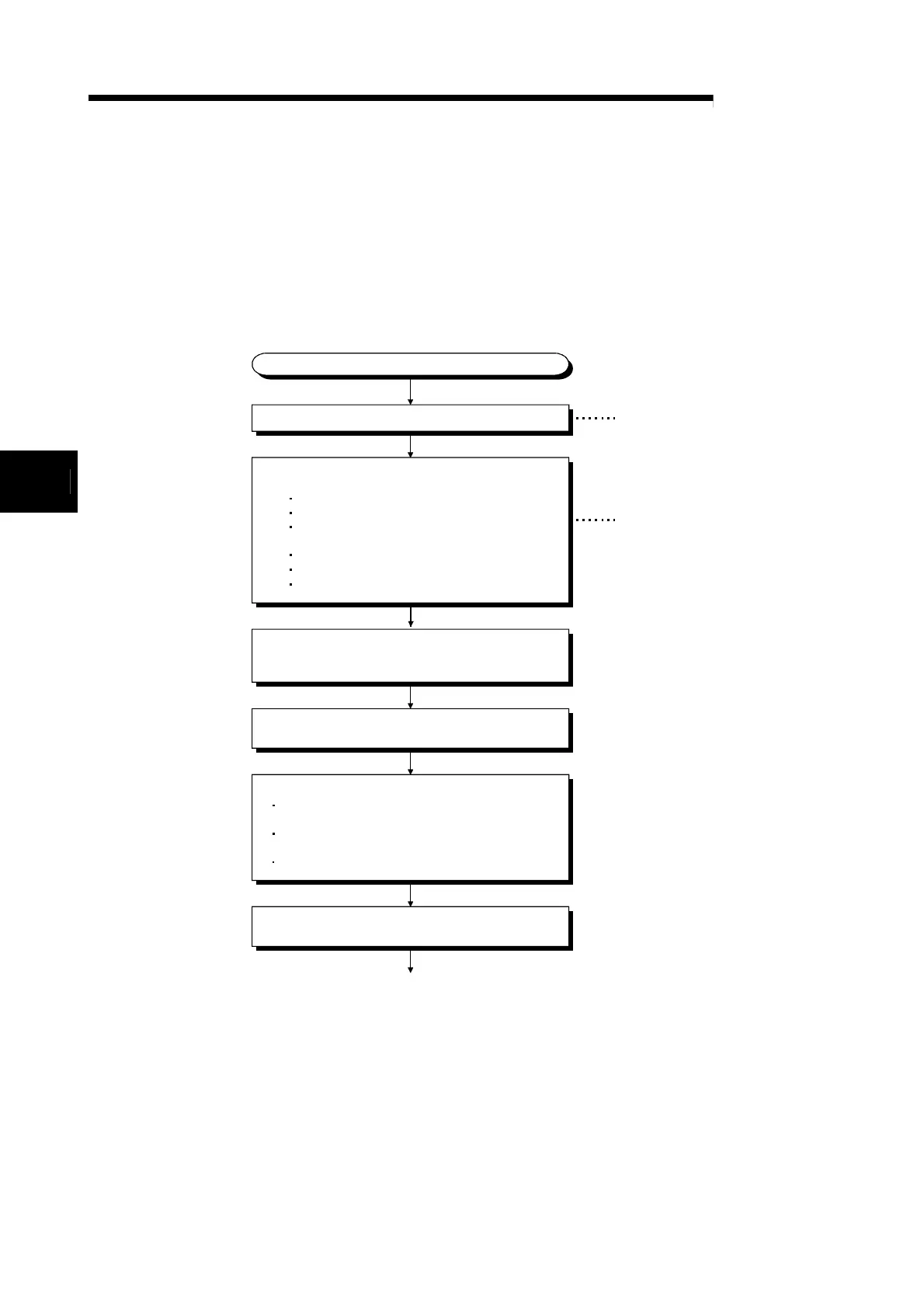
The following flowchart indicates the procedure to start the data link of the system
using the AJ65SBT-CLB.
Start
Check prior to power-on
Confirm the power supply voltage (24V DC) to be
input to the power supply adaptor.
Check that the RUN/STOP switch of the PLC CPU
is in the "STOP" position.
Check for overlapping remote station numbers.
Mount the AJ65SBT-CLB to the control panel or device.
Set the switches, etc. of the AJ65SBT-CLB.
(1) CC-Link side
Station number
Transmission speed
Number of occupied stations
(2) CC-Link/LT side
Point mode setting
Transmission speed
Self-loopback test setting
Connect the modules on the CC-Link/LT side with
dedicated flat cables. Connect terminating resistors
to the ends of the trunk line.
Connect the dedicated power supply or power
supply adaptor of CC-Link/LT.
Power on CC-Link/LT.
Confirm that the PW LED of the AJ65SBT-CLB turns on.
To the next page
Refer to Section 4.2
Refer to Section 4.3
4

 Loading...


