12 - 50
12.3 Error Code List
12.3.8 Error code list (8000 to 9000)
12
TROUBLESHOOTING
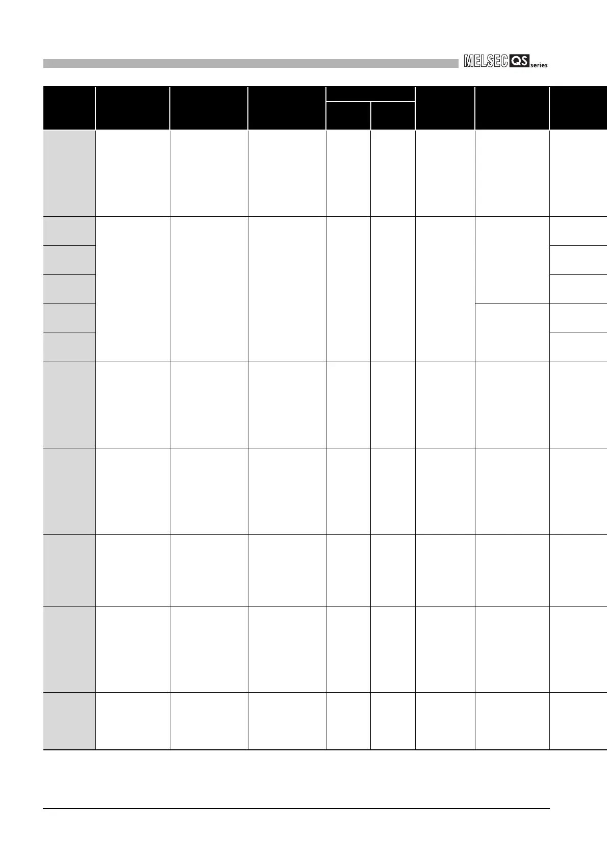
8060
INCORRECT
FIRMWARE
–
Error
information
Off Flash Stop
At power ON/
At reset/When
an END
instruction
executed.
8070
INTERNAL
CPU
COMMUNI-
CATION
ERROR
–
Error
information
Off Flash Stop
At power ON/
At reset
8071
8072
8073
When an END
instruction
executed.
8074
8080
POWER
SUPPLY
ERROR
–
Error
information
Off Off/On Stop Always
8090
VOLTAGE
DIAGNOSIS
ERROR
–
Error
information
Off Flash Stop
When an END
instruction
executed.
8100
TEST MODE
TIME
EXCEEDED
– – On On Continues
When an END
instruction
executed.
8120
WDT CLOCK
CHECK
ERROR
– – Off Flash Stop Always
8300
CC-LINK
REMOTE
DETECTION
ERROR
CC-Link Safety
information
CC-Link Safety
information
Off/On
*1
Flash/
On
*1
Stop/
Continues
*1
Always
Error
Code
(SD0)
Error
Message
Common
Information
(SD5 to 15)
Individual
Information
(SD16 to 26)
LED Status CPU
Operation
Status
Diagnostic
Timing
RUN ERROR
*1 The operating status of a CPU module in case of an error can be set in the "Operation settings during remote station error" of "Parameter". The default is set
to "Stop" (The LED indication changes according to the status).
*2 At occurrence of "F****", the “USER” LED turns on.

 Loading...

