2 - 4 2 - 4
MELSEC-Q
2 SYSTEM CONFIGURATION
2.2 Multiple Remote I/O Network (QnPHCPU Only)
2.2.1 Configuration
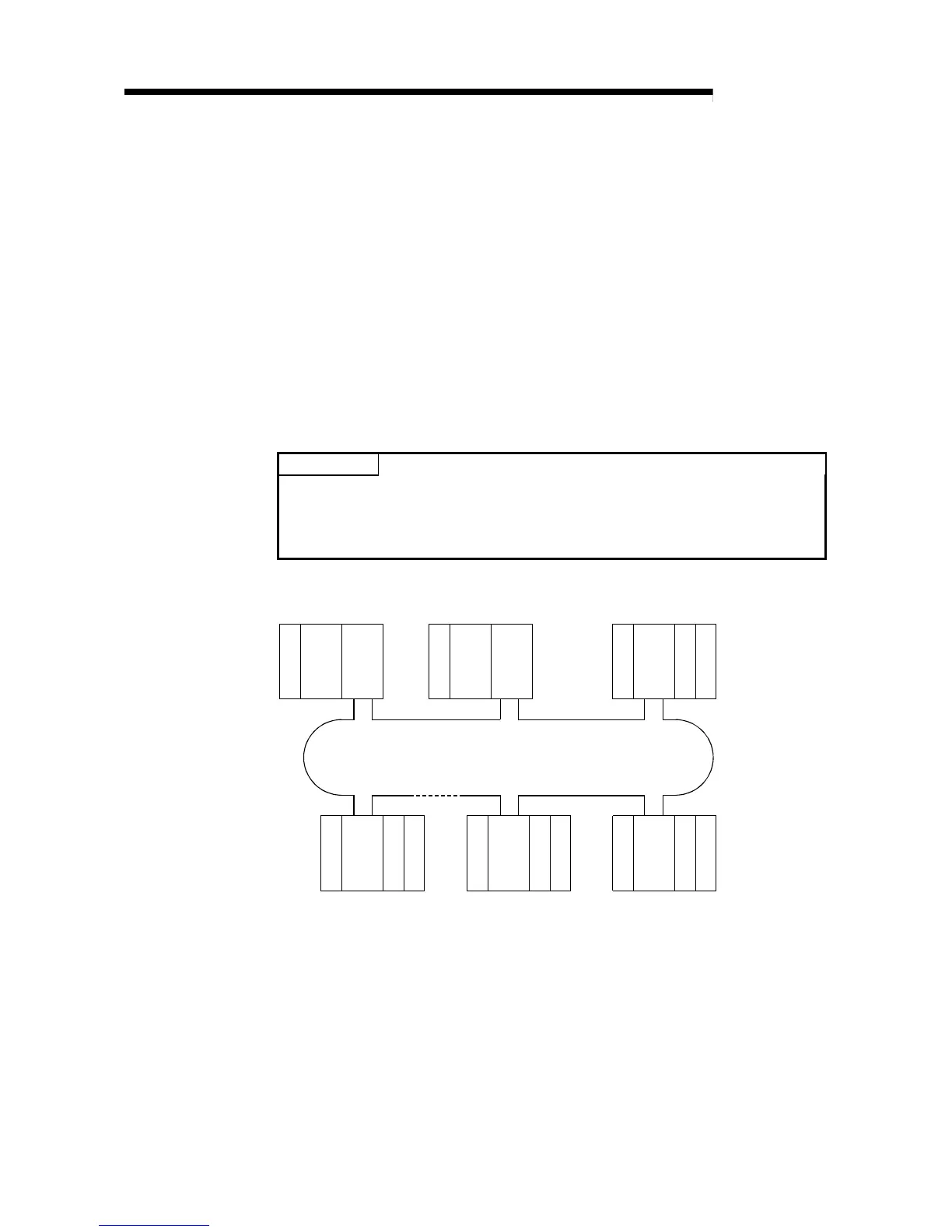
A multiplexed remote I/O network system includes a multiplexed remote master station
and a multiplexed remote sub-master station. The multiplexed remote sub-master
station takes control of remote I/O stations when the multiplexed remote master station
fails.
Always assign station No. 0 to the multiplexed remote master station.
It is allowed to assign any of station number 1 to 64 to the multiplexed remote sub-
master station, provided that the number does not overlap with that of remote I/O
station.
63 remote I/O stations can be connected in an optical loop system, 31 stations in a
coaxial bus system.
POINT
Only the QnPHCPU is the CPU module that works as a multiplexed remote master
station and multiplexed remote sub-master station.
The Q02CPU, Q02HCPU, Q06HCPU, Q12HCPU and Q25HCPU do not work as a
multiplexed remote master station and multiplexed remote sub-master station.
QnPH
CPU
QJ71
LP21
I/OQJ72
LP25
I/O
I/OQJ72
LP25
I/O I/OQJ72
LP25
I/OI/OQJ72
LP25
I/O
QnPH
CPU
QJ71
LP21
Station No. 0
(Multiplexed remote
master station)
Power supply
Station No. 1
(Multiplexed remote
sub-master station)
Station No. 2
(Remote I/O station)
Power supply
Optical fiber cable
Station No. 64
(Remote I/O station)
Station No. 4
(Remote I/O station)
Station No. 3
(Remote I/O station)
Power supply
Power supply
Power supply
Power supply
Up to 63 remote I/O stations can be connected in an optical loop system.
Up to 31 stations can be connected in a coaxial bus system.
 Loading...


