4 - 2 4 - 2
MELSEC-Q
4 SETUP AND PROCEDURES BEFORE STARTING THE OPERATION
4.2 Network Module Names and Settings
4.2.1 QJ71LP21, QJ71LP21-25, QJ71LP21G, QJ71LP21GE, QJ71BR11 (Remote master
station)
MNG
D.LINK
RD
L ERR.
RUN
T.PASS
SD
ERR.
QJ71LP21-25
0
5
0
5
STATION NO.
X10
X1
MODE
0
8
C
4
QJ71LP21
-25
IN
OUT
EXT.PW
+24V
24G
24G
0
5
9
4
8
3
7
2
6
1
0
5
9
4
8
3
7
2
6
1
STATION NO.
X10
X1
MODE
0
8
F
7
E
6
D
5
C
4
B
A
3
2
9
1
IN
OUT
MNG
D.LINK
RD
L ERR.
RUN
T.PASS
SD
ERR.
QJ71LP21S-25
QJ71LP21S-25
EXT.PW
EXT.PW
+24V
24G
(FG)
MNG
D.LINK
RD
L ERR.
RUN
T.PASS
SD
ERR.
0
5
0
5
STATION NO.
X10
X1
MODE
0
8
C
4
QJ71BR11
QJ71BR11
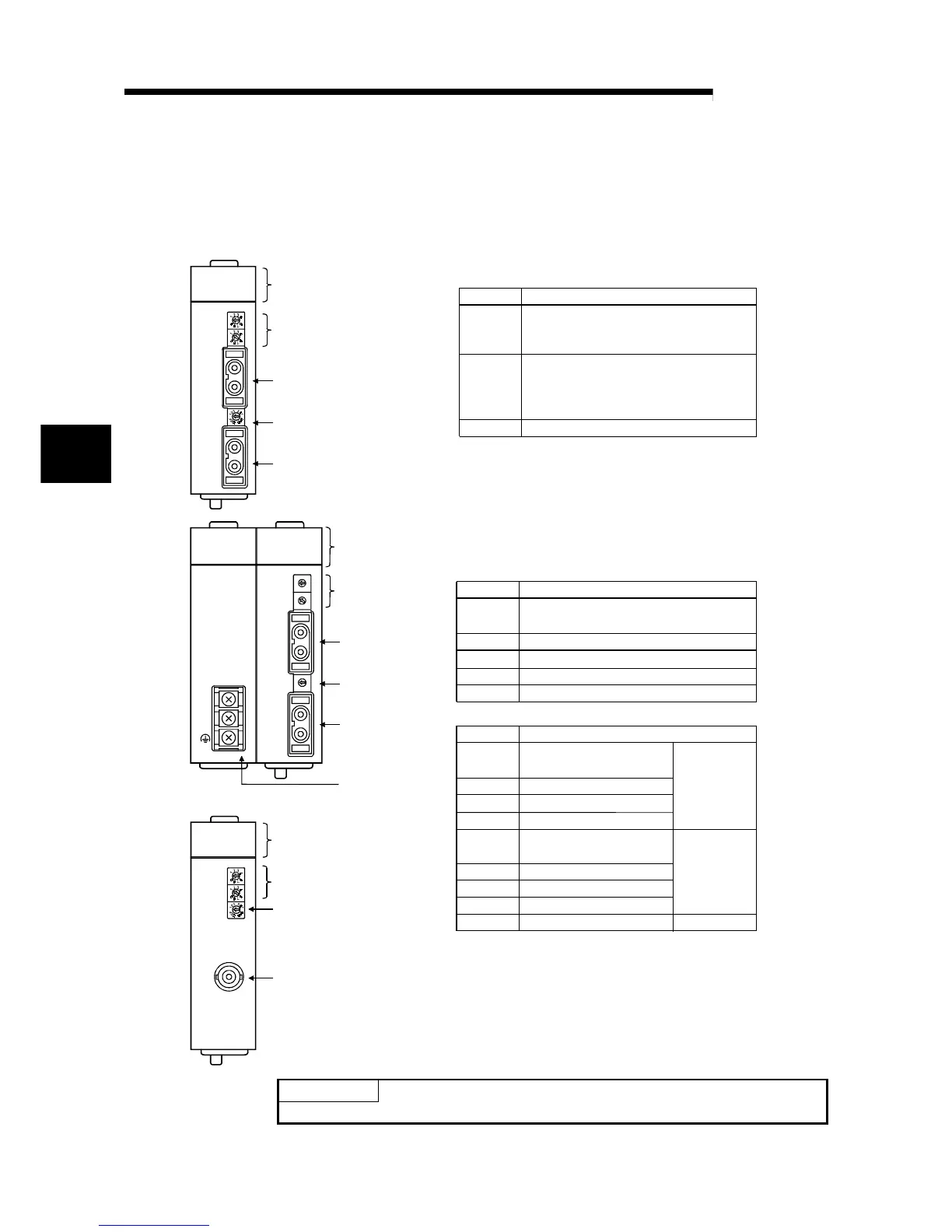
2) STATION No. (factory default setting: 1):
Station number setting switch
This switch sets the station number on the same network.
The red ERR.LED lights up for a setting error.
Setting
0
1 to 64
65 to 99
Setting of a remote sub-master station
Setting error
Remote master station setting
Description
Setting
0
Description
Online (Mode selected with a parameter
becomes valid.)
Self-loopback test
Use prohibited
Hardware test
Internal self-loopback test
1
2
3
4 to F
4) MODE (factory default setting: 0): Mode setting switch
5) Coaxial connector
Connect an F-type connector for a coaxial cable
This switch sets the operation mode.
a) QJ71LP21, QJ71LP21G, QJ71LP21GE, QJ71BR11
3) IN/OUT connectors
Connected with an optical fiber connector.
(IN connector)
For forward loop receiving/reverse loop sending
(OUT connector)
For forward loop sending/reverse loop receiving
b) QJ71LP21-25, QJ71LP21S-25
Setting
0
Description
Online (Mode selected with
a parameter becomes valid.)
Self-loopback test
Hardware test
Internal self-loopback test
1
2
3
When 10Mbps
in use
Self-loopback test
Use prohibited
Hardware test
Internal self-loopback test
5
6
7
8 to F
4
Online (Mode selected with
a parameter becomes valid.)
When 25Mbps
in use
6) External power supply terminal block
Wire for external power supply.
2) (Same as the optical
loop module)
Coaxial cable bus module
Optical loop module
1) LED displays
2)
3)
4)
3)
1) LED displays
5)
4) (Same as the optical
loop module)
1) LED
displays
2)
3)
4)
3)
6)
POINT
Set the mode setting switches in the same position on all network modules.
4
 Loading...


