App - 11 App - 11
MELSEC-Q
APPENDIX
Appendix 3 Link Special Register (SW) List
In the link special register, the data linking information is stored as numeric values.
Thus, faulty areas and causes of errors can be checked using or monitoring the link
special registers in the sequence programs.
Moreover, the link special register (SW) that stores the link status is used for the
detailed information of the network diagnostics of GX Developer. For a list of the device
numbers for each display item, see Section 8.1, "Network Diagnostics (Line Monitor)."
When multiple network modules are installed, the SW of each network module is
refreshed to the corresponding SW of the CPU module if each network module’s
refresh parameters are not set. If the refresh parameters are set for at least one network
module, the refresh parameters of all the network modules should be reviewed.
Module installing position Module 1 Module 2 Module 3 Module 4
Device number SW0000 to 01FF SW0200 to 03FF SW0400 to 05FF SW0600 to 07FF
The link special register has the user setting area range (SW000 to SW001F) and the
system setting area range (SW0020 to SW01FF). (When the module is installed in the
position of Module 1)
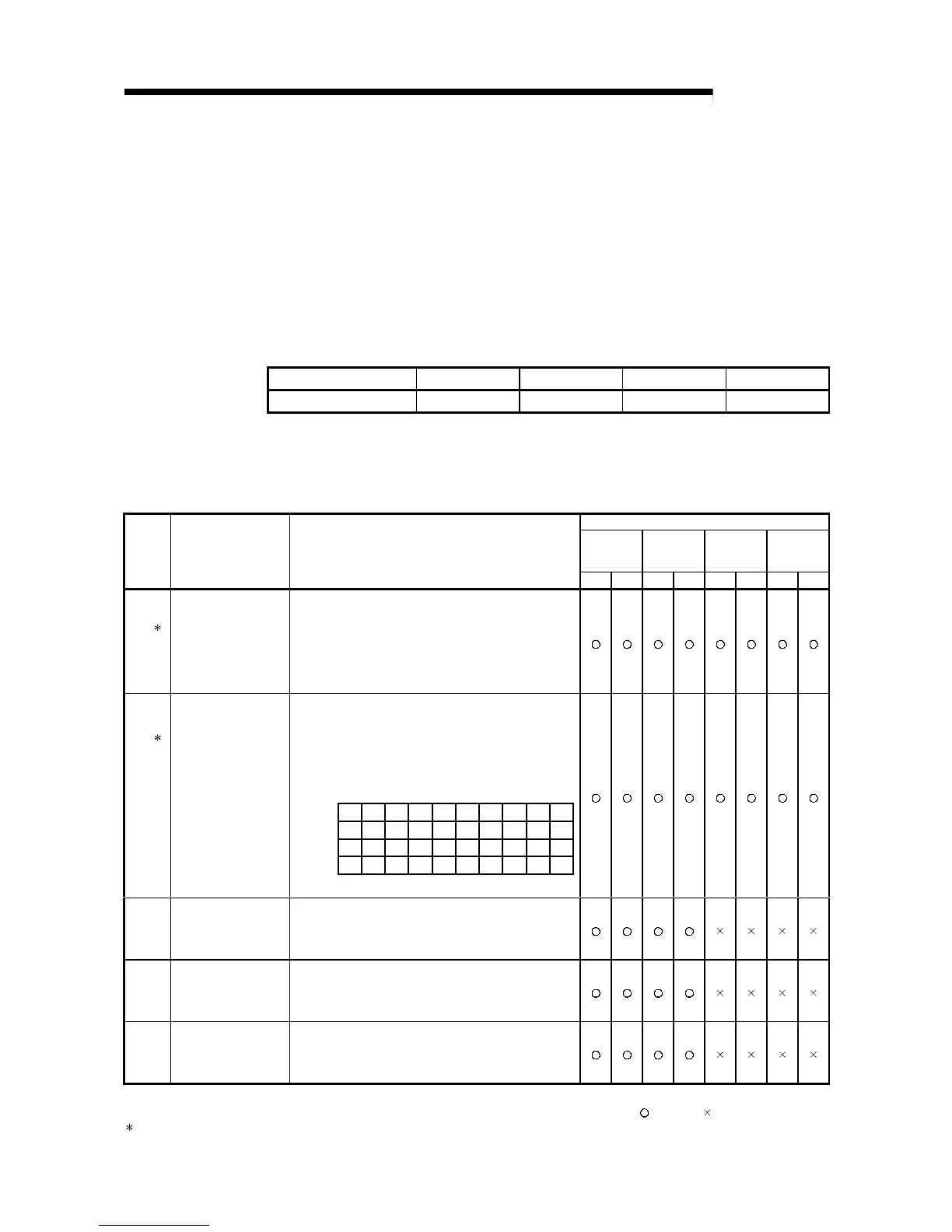
Table 2 Link special register (SW) list
Use permitted/prohibited
Control
station
Normal
station
Remote
master
station
Remote I/O
station
No. Name Description
Optical Coaxial Optical Coaxial Optical Coaxial Optical Coaxial
1
SW0000
(0)
Link stop/startup direction
content
Sets the station that stops/restarts data linking.
00
H: Host
01
H
: All stations
02
H
: Designated station
80
H: Host (forced stop/restart)
81
H
: All stations (forced stop /restart)
82
H
: Designated station (forced stop /restart)
1
SW0001
(1)/
SW0002
(2)/
SW0003
(3)/
SW0004
(4)
Link stop/startup direction
content
Sets whether the designated station should execute data linking.
(When the SW0000 is 02
H
or 82
H
.)
Sets the bits to 1 for stations whose data linking is
stopped/restarted.
0: Invalid data linking stop/restart instruction
1: Valid data linking stop/restart instruction
16
32
48
64
15 14 13
5
4
3
21
31 30
47 46
63 62
29
45
61
21 20 19 18 17
37 36 35
34
33
53 52 51 50 49
to
to
to
to
b15 b14 b13 b12 b4 b3 b2 b1 b0
SW0001
SW0002
SW0003
SW0004
The numbers 1 to 64 in the above table
indicate the station numbers.
to
Sets the logical channel number for physical channel number 1.
(Valid only for channels on the receiving side)
0 : Logical channel number 1 (default)
SW0008
(8)
Logical channel setting
(channel 1)
1 to 64 : Other logical channel number is set.
Sets the logical channel number for physical channel number 2.
(Valid only for channels on the receiving side)
0 : Logical channel number 2 (default)
SW0009
(9)
Logical channel setting
(channel 2)
1 to 64 : Other logical channel number is set.
Sets the logical channel number for physical channel number 3.
(Valid only for channels on the receiving side)
0 : Logical channel number 3 (default)
SW000A
(10)
Logical channel setting
(channel 3)
1 to 64 : Other logical channel number is set.
[Availability column] Optical: optical loop, Coaxial: coaxial bus
: Available, : Not available
1: Used in the network test of GX Developer.
 Loading...