App - 12 App - 12
MELSEC-Q
APPENDIX
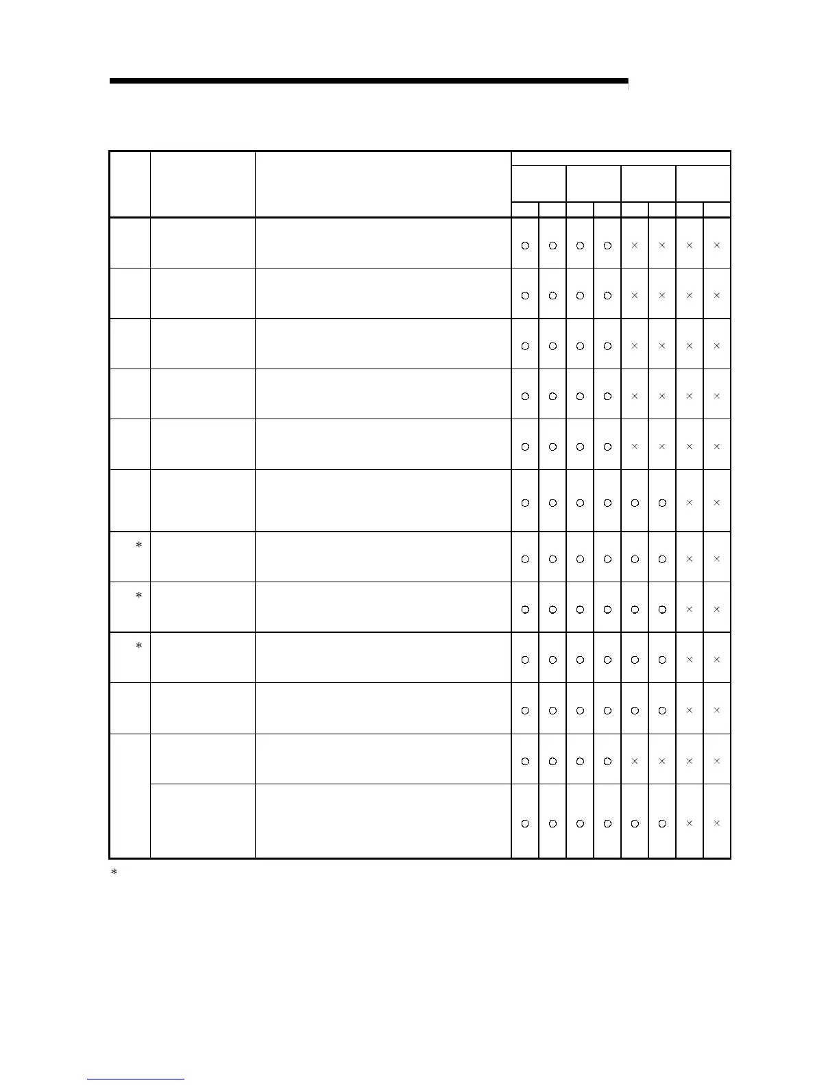
Table 2 Link special register (SW) list (Continued)
Use permitted/prohibited
Control
station
Normal
station
Remote
master
station
Remote I/O
station
No. Name Description
Optical Coaxial Optical Coaxial Optical Coaxial Optical Coaxial
Sets the logical channel number for physical channel number 4.
(Valid only for channels on the receiving side)
0 : Logical channel number 4 (default)
SW000B
(11)
Logical channel setting
(channel 4)
1 to 64 : Other logical channel number is set.
Sets the logical channel number for physical channel number 5.
(Valid only for channels on the receiving side)
0 : Logical channel number 5 (default)
SW000C
(12)
Logical channel setting
(channel 5)
1 to 64 : Other logical channel number is set.
Sets the logical channel number for physical channel number 6.
(Valid only for channels on the receiving side)
0 : Logical channel number 6 (default)
SW000D
(13)
Logical channel setting
(channel 6)
1 to 64 : Other logical channel number is set.
Sets the logical channel number for physical channel number 7.
(Valid only for channels on the receiving side)
0 : Logical channel number 7 (default)
SW000E
(14)
Logical channel setting
(channel 7)
1 to 64 : Other logical channel number is set.
Sets the logical channel number for physical channel number 8.
(Valid only for channels on the receiving side)
0 : Logical channel number 8 (default)
SW000F
(15)
Logical channel setting
(channel 8)
1 to 64 : Other logical channel number is set.
Set the time from the occurrence of a data link error to the
recognition of data link stop in the redundant system.
0 : 2 seconds (default)
SW0018
(24)
System switching
monitoring time setting
1 to 500
: Units of 10 ms (Units of 10 ms for 10 ms to 5
seconds)
Indicates the change of the number of retries for the time of the
issue of a request in send and receive instructions.
0 : 7 times (default)
2
SW001C
(28)
Number of retries
1 to 7 : Setting exists
Indicates the change of the retry interval for the time of the issue
of a request in send and receive instructions.
0 : 100 ms (default)
2
SW001D
(29)
Retry interval
1 to FE
H
: Setting exists (unit: ms)
Indicates the change of the number of gates for the time of the
issue of a request in send and receive instructions.
0 : 7 (default)
2
SW001E
(30)
Number of gates
1 to EF
H
: Setting exists
Stores the status of the network module.
0: Normal
Other than 0 : Abnormal (see the error codes in Section 8.3)
SW0020
(32)
Module status
FF : Module error
Indicates the processing result of the ZNRD instruction.
0 : Normal completionZNRD instruction
processing result
Other than 0 : Abnormal completion (see the error codes in
Section 8.3)
Indicates the processing results of the SEND/RECV/READ/
WRITE/REQ/RECVS/RRUN/RSTOP/RTMRD/RTMWR/REMFR/
REMTO instructions (when physical channel 1 is used).
0 : Normal completion
SW0031
(49)
Send/receive instruction
(1) processing result
Other than 0 : Abnormal completion (see the error codes in
Section 8.3)
2: Valid only when SB0047 is off. When it turns on (error), the last data are retained.
 Loading...