2 - 8 2 - 8
MELSEC-Q
2 SYSTEM CONFIGURATION
2.3.2 Setting items
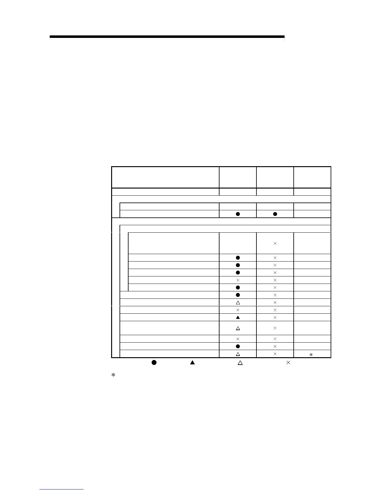
(1) Table 2.5 indicates the parameter setting items of the multiplexed remote master
station (DM
R
) and multiplexed remote sub-master station (DSM
R
).
In the redundant system, the same network parameters are set to both the
control and standby systems. For this reason, parameter setting for the
multiplexed remote sub-master station is not required.
Make sure to assign No.0 to the network module mounted on the system A, i.e.,
the system to which the system A connector of tracking cable is connected within
the redundant system.
Table 2.5 Setting Items of Multiplexed Remote Master Station and
Multiplexed Remote Sub-master Station
Setting items
Remote master
station (M
R
)
Remote
submaster
station (DSM
R
)
Reference
Tracking cable connector System A System B Section 7.1.1
Network module switch
STATION NO. 0 1 to 64 Section 4.2.1
MODE Section 4.2.1
Parameter setting on GX Developer
MELSECNET/H Ethernet card settings
Network type
MELSECNET/H
(Remote master
station)
Section 5.1.1
Starting I/O No.
Section 5.1.2
Network No.
Section 5.1.2
Total stations
Section 5.1.2
Group No.
—
Mode
Section 5.1.2
Common parameters
Section 5.1.3
Auxiliary setting
Section 5.1.4
Station specific parameters
—
Refresh parameters
Section 5.1.5
Valid module number during other station
access
Section 5.1.6
Interlink data transfer parameters
—
Setting of redundant configuration
Section 5.1.7
Routing parameters
2
: Always set,
:
Default setting,
:
Set as needed,
:
No need to set
1: Refer to the "Q Corresponding MELSECNET/H Network System Reference
Manual (PLC to PLC Network) (SH-080049)".
 Loading...


