Chapter Four: Operation How to Select U
stream Control
49
How to Select Upstream Control
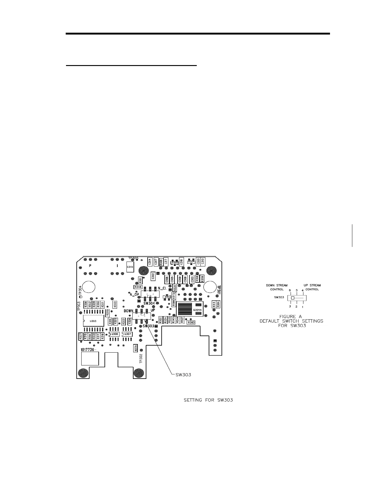
The 640B Series controller is configured for downstream control when it leaves the factory. To
use it in a upstream control application, you must remove the enclosure cover and reposition
switch SW303 on the Control board.
1.
Stop the gas flow through the 640B Series controller.
2.
Remove I/O cables attached to the connector on the 640B Series controller.
3.
Use a
3
/16” hex wrench (or open-ended wrench) to remove the hex nuts on each side of the
I/O connector. Remove the 4 Phillips head screws from the sides of the enclosure. Refer
to Figure 3, page 17, for the location of the hex nuts on the I/O connector. Place the hex
nuts and screws aside for safe keeping.
4.
Position the controller with the back side facing you and pull up on the enclosure to
remove it.
The back side of the unit lists the I/O connector pinout. The board assembly will be
visible, with the back of the Control board facing you. The Transducer board is
connected to the front of the Control board.
5.
Locate the switch labeled “SW303” in the middle section of the Control board.
Refer to Figure Error! Bookmark not defined. for the location of the switch.
Figure 21: Switch Settings on the Control Board