Gas Pressure and Control Chapter Two: Installation
16
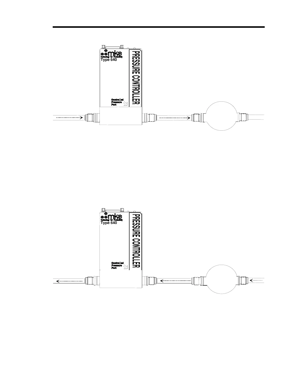
Controlled
Volume
Downstream Pressure Control
Gas Flow
Figure 1: Downstream Pressure Control
The 640B Series controllers are shipped from the factory configured for downstream pressure
control. Refer to Table 8, page 28, for the initial configuration of the unit.
Upstream Pressure Control
Upstream pressure control occurs when the 640B Series controller is positioned after the
controlled pressure volume in the gas flow path, so that the controlled volume is upstream of the
640B Series controller. The gas from the pressure system enters the controller on the transducer
side, labeled “Controlled Pressure Port.” Figure 2 shows the gas flow for upstream control.
Controlled
Volume
Gas Flow
Upstream Pressure Control
Figure 2: Upstream Pressure Control
The 640B Series controllers are shipped from the factory configured for downstream pressure
control. To configure the pressure controller for upstream control, you must change switch
settings inside the unit. Refer to How to Select Upstream Control, page 49, for instructions.