3.7.2 Signal Output Pins
When an event is detected, the MOBOTIX camera can switch the signal output
(pin1). Use the corresponding options in Setup Menu> Actions to specify how
long the camera should close the signal output.
• Off: Signal output is open (10kOhms on 3.3V).
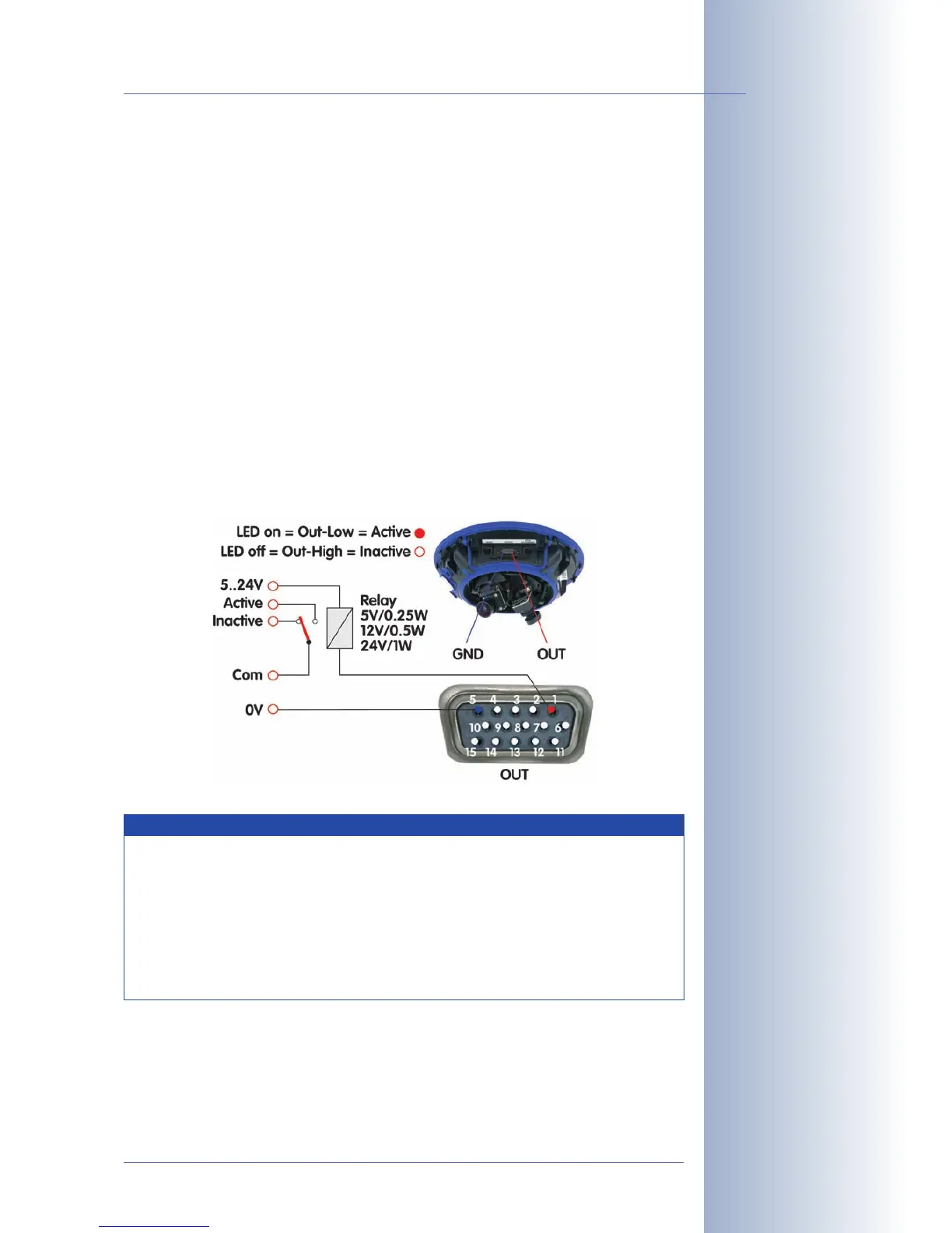
• 1s, 2s, 5s, 10s, 30s, 1min, 5min: Closes the contact between pin1 of the D
Sub 15 connector and ground (pin5). The signal output is protected against
power surges and unwanted feedback (±48V) and switches up to 50mA. It
can thus switch a 12V relay with 0.6W and a 24V relay with 1,2W.
Open Setup Menu> Enhanced Signal Out Options to set custom switching times
for any combination of events (not Web models). This dialog also allows using a
time table and setting a dead time.
Click on Admin Menu> LED Setup and set one or more LEDs to
Signal input
to dis-
play the state of the input signal for testing (
Signal input
option: loop closed = LED
on).
© MOBOTIX AG • Security-Vision-Systems • Made in Germany
www.mobotix.com • sales@mobotix.com
123/132
D12 Camera Manual Part 1
Activate the signal output
in Admin Menu> LED
Setup or for specific
events in Setup Menu>
Event Settings
The event settings allow
activating the signal out-
put for a certain time only
(e.g. to generate an
impulse)
Example setup
Select the trigger condi-
tion:
- Open (high)
- Closed (low)
- Rising (low to high)
- Falling (high to low)
- Change:
(rising or falling)
Besides detecting the
current state (open or
closed), you may also trig-
ger upon rising, falling or
changing signal flanks.
Notes
In contrast to the signal output pins of the RS232 interface (pins3 and
7), the signal output pin 1 assumes an inactive state and will stay
inactive while the camera is booting.
The
Pin-Out of MX Interface Connector D Sub 15 HD
table in section
3.7.1,
MX Interface Connector for Direct Connections
, contains a
detailed explanation of the individual pins.