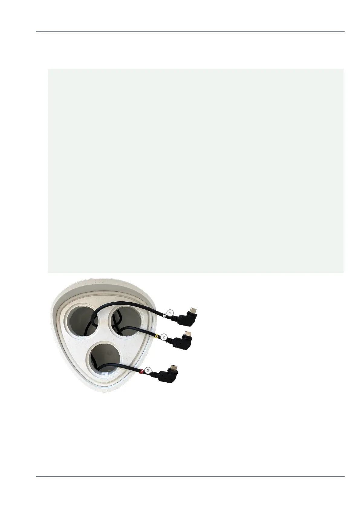
3. Properly assign the sensor module cables.
The sensor module cables are numbered (small colored rings next to the connectors, see figure below).
CAUTION!
When attaching sensor modules, make sure that these rules are followed:
n
The MOBOTIXMOBOTIX M73 can be equipped with these types of modules:
n
A maximum of two optical modules can be used.
n
A maximum of two functional modules can be used.
n
One thermal module can be used instead of one optical module (see Installing the Sensor
Modules to the Thermal Front Plate, p. 55).
Applicable to newer thermal sensor module types Mx-O-M7SB-640R050, Mx-O-M7SB-640T050, Mx-O-
M7SB-336R100, MX-O-M7SB-336T100 (see Technical Specifications, p. 22):
n
Use the following sensor module cables for these types of modules:
n
Cables ① and ② :Optical, functional or thermal modules. No audio module.
n
Cable ③ :Functional or thermal modules. No optical modules.
Applicable to other thermal sensor module types (see Technical Specifications, p. 22):
n
Use the following sensor module cables for these types of modules:
n
Cables ① and ② :Optical or functional modules. No thermal modules, no audio mod-
ule.
n
Cable ③ :Functional or thermal modules. No optical modules.
When positioning the modules, you are free to choose the individual module positions (with the excep-
tion of the thermal sensor module, since it is pre-installed on a special front plate).
Fig. 8: Numbered sensor module cables
Mounting
Installing the Sensor Modules
40 / 110