MSD Single-Axis System Operation Manual AC-AC Servo Drive
ID no.: CA65642-001 06/2018
moog
15
Mechanical installation
3 Mechanical installation
The device is designed only for installation in a stationary switch cabinet. The switch
cabinet must as a minimum provide IP4x protection. According to ENISO13849-2 the
switch cabinet must have IP54 protection or higher when using the safety function STO
(Safe Torque Off).
3.1 Notes for installation
CAUTION Damage to the device due to incorrect installation conditions!
The device may suffer irreparable damage.
For this reason
• Moisture must not be allowed to enter the device
• There must not be any aggressive or conductive substances in the ambient air
• Foreign bodies such as drilling chips, screws, washers etc. must not be allowed to fall into
the device
• The ventilation openings must not covered
Note the following points:
y Cooling air must be able to ow through the device without restriction.
y On installation in switch cabinets with convection (= heat loss is dissipated to the outside via the
cabinet walls), always t an internal fan.
y The backing plate must be well-earthed.
y The device is intended only for vertical installation in switch cabinets. The switch cabinet must as
a minimum provide IP4X protection.
y To attain the best result for effective EMC installation you should use a chromated or galvanised
backing plate. If backing plates are varnished, remove the coating from the contact area! The
devices themselves have an aluminium back panel (Size 1 to Size 4) or a back panel made of
galvanised sheet steel (Size 5 to Size 7).
y Maximum pollution degree2 according to IEC/EN60664-1.
y The servo drives must not be installed in areas where they would be permanently exposed to
vibration. You will nd more information in the appendix, Table A.20.
y The device heats up during operation and the temperature on the heat sink may reach +100°C
(+212°F). Pay attention to this aspect for neighbouring components.
NOTE
According to ENISO13849-2 the switch cabinet must have IP54 protection
or higher on using the STO (Safe Torque OFF) safety function.
3.2 Mounting (air and liquid cooling)
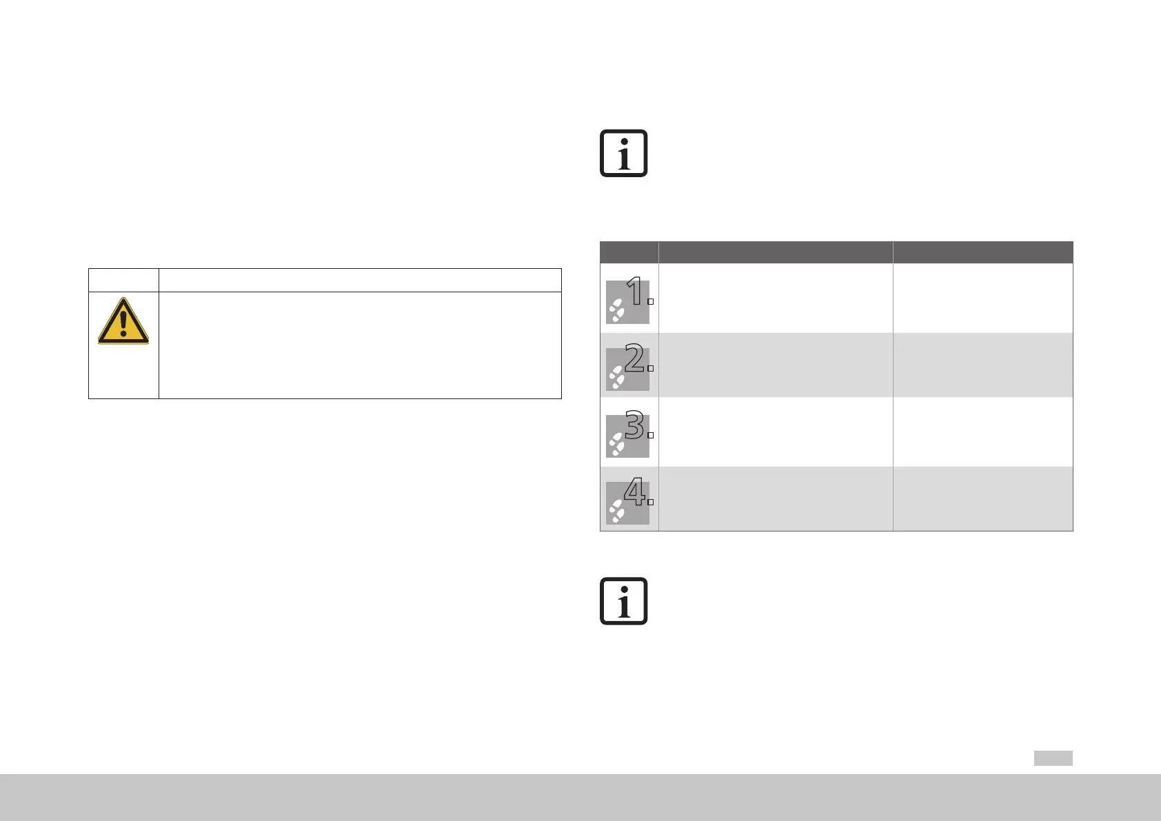
Step Action Comment
Mark out the position of the tapped holes and the pipe
ttings, if necessary, on the backing plate.
Drill holes and cut a thread for each xing screw in the
backing plate.
Pay attention to the mounting clearances!
Pay attention to the bending radius of the
connection cables!
For dimensional drawings/hole spacing
see Figure3.2 to Figure3.5
Mount the servo drive vertically on the backing plate.
Observe the mounting clearances!
The contact area must be bare metal.
On devices with liquid cooling, while screwing the hose
connections (not included in the scope of supply) into
the pipe ttings, lock the pipe ttings using a 22mm
(0.87in) open-ended wrench to prevent damage due to
the application of torque to the device.
Pay attention to a perfectly sealed
connection without leaks
(e.g. using Teon sealing tape)!
Mount the other components, suchas the mains lter,
mains choke etc., on the backing plate.
The cable between mains lter and
servo drive may be maximum 300 mm
(11.81in) long.
Table 3.1 Mechanical installation
NOTE:
Connect the ow from the liquid cooling for Size 7 to the connection
correspondingly marked (Figure 3.6). For Size 3 to Size 6A the connection can
be chosen as required.
 Loading...


