MSD Single-Axis System Operation Manual AC-AC Servo Drive
ID no.: CA65642-001 06/2018
moog
57
Diagnostics
6 Diagnostics
6.1 Status indication on the device
The device states are shown on the device using the 7-segment display.
6.1.1 Device states
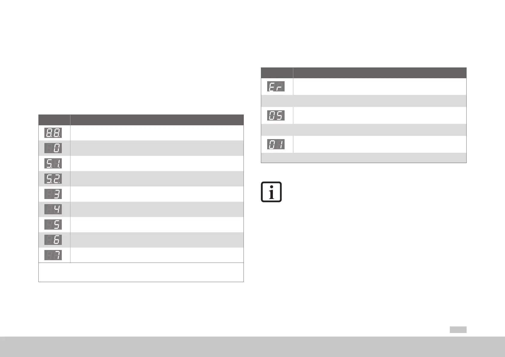
Display System state
Device in reset state
Self-initialisation on device startup
*)
Not ready to switch on (no DC link voltage)
1)
*)
Start inhibit (DC link OK, power stage not ready)
1)
Ready to switch on (power stage ready)
Switched on (power applied to drive)
2)
Drive ready (power applied to drive and drive ready for reference value input)
2)
Quick stop
2)
Error response active
2)
*) Not a "safe indication" as specied in IEC/EN61800-5-2.
1) S. ashes if the function STO (Safe Torque Off) is active, indication extinguishes if function is inactive.
2) The point ashes if the power stage is active.
Table 6.1 Device states
6.1.2 Error indication
The specic error codes are indicated via the 7-segment display. Each error code
comprises the alternating sequence ►"Er" ►error number ►error location.
Display Meaning
Device error
↓ Display changes after approx. 1s
Error number (decimal)
Example: 05 = Overcurrent
↓ Display changes after approx. 1s
Error location (decimal)
Example: 01 = Hardware monitoring
↑ After approx. 1s the display changes back to ER
Table 6.2 Display of the error code
NOTES:
y Acknowledging error
The errors can be acknowledged according to their programmed reaction
(ER) or only by means of a +24V reset (X9/X10) (ER.). Errors marked with a
point can only be reset once the cause of the error has been rectied.
y Error code
You will nd detailed information on the error codes and on error
management in the "MSDServoDrive Device Help".
 Loading...


