16
Mechanical installation
MSD Single-Axis System Operation Manual AC-AC Servo Drive
ID no.: CA65642-001 06/2018
moog
3.3 Dimensions, devices with air cooling
MSD
ServoDrive
AC-AC
Size 1 Size 2 Size 3 Size 4 Size 5 Size 6 Size 6A
G392-004A
G392-004
G392-006
G392-008
G392-012
G392-016
G392-020
G392-024
G392-032
G392-045
G392-060
G392-072
G392-090
G392-110
G392-143
G392-170
Weight [kg] 3.4 4.9 6.5 7.5 13 28 32
B (width) 58.5 90 130 171 190 280
H (height)
1)
295 345 540
T (depth)
1)
224 238 242 322
A 29.25 50 80 120 150 200
C 344.5 365 581
C1 5 6 10
DØ 4.8 5.6 9.5
Screws 2xM4 4xM4 4xM5 4xM8
E 2 20 40
F
2)
≥100 ≥150 ≥180
G
2)
≥270 ≥300 ≥500
H1 355 382.5 600
H2 38.5 15 20
All dimensions in mm
1) Without terminals, connectors and shield plates
2) If necessary take into account larger bending radii for connection cables.
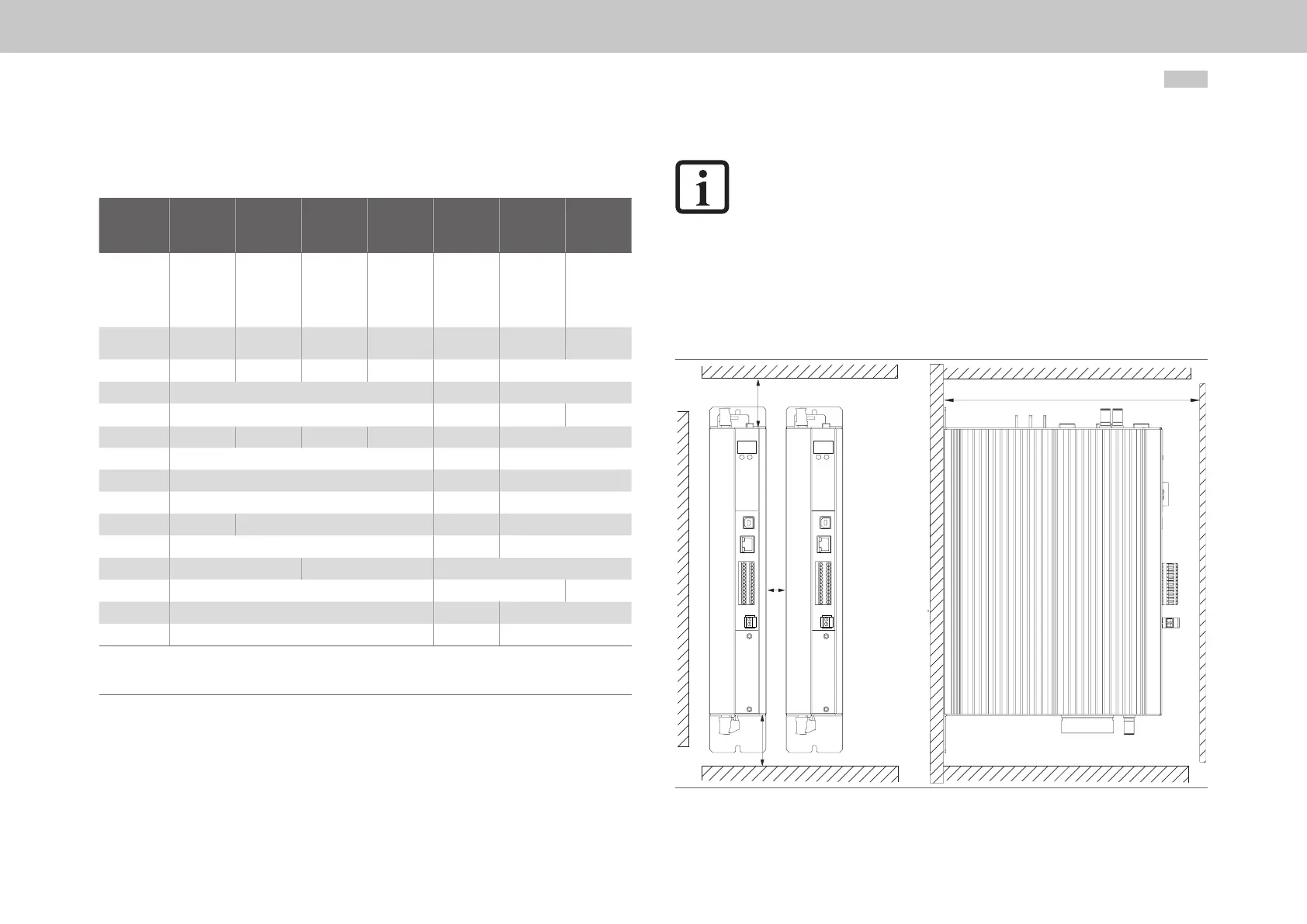
Table 3.2 Dimensions, housing with air cooling, see Figure3.1 and Figure3.2
NOTE:
The minimum distance "E" specied in the table for sizes 1-4 applies for
devices of the same power rating. On butt mounting devices with different
drive powers, you should arrange the devices in order by power rating
(e.g., viewed from the left, Size 4-Size 3-Size 2-Size 1). This arrangement will
minimise the thermal interaction.
On butt mounting MSDServoDrives with other devices, you should ensure
there is no thermal interaction between the devices.
3.3.1 Mounting clearances
E
G
F
F
Figure 3.1 Mounting clearances for air cooling, schematic depiction for Size 1 to Size 6A
 Loading...


