40
Electrical installation
MSD Single-Axis System Operation Manual AC-AC Servo Drive
ID no.: CA65642-001 06/2018
moog
4.13 Option 2 (Technology)
Option2 can be factory-congured with various technology options. Additional or special
encoders can be evaluated here for example.
You will nd all available options in the MSDServoDrive Ordering Catalog. The user
manuals for the respective options provide detailed information on commissioning.
4.14 Encoder connection
All encoder connections are located on the top of the unit.
Resolver
high-resolution encoder
Variant
C
X (optional X )
78
X
6
Variant
B
Variant
A
high-resolution encoder
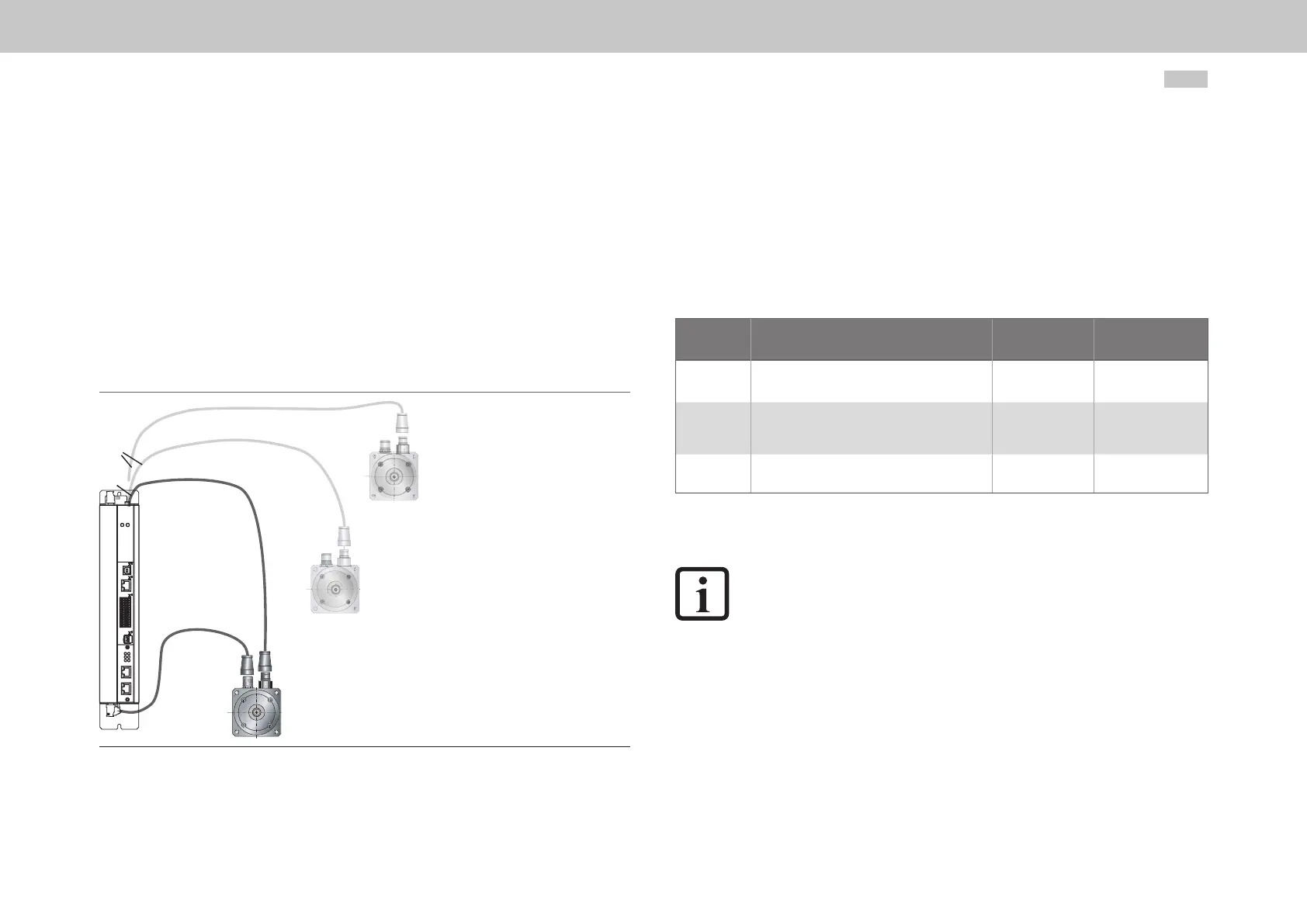
Figure 4.18 Motor/encoder cable assignment
4.14.1 Encoder connection for servo motors
Please use the ready made motor and encoder cables from Moog to connect the servo
motors.
4.14.2 Allocation of motor/encoder cable to the servo drive
Compare the rating plates of the components. Make absolutely sure you are using the
correct components according to variant A, B or C!
Motor (with encoder installed) Encoder cable
Servo drive
connection
VariantA
With resolver
without further options
CO8335-013-yyy X6
VariantB
Sin/Cos multiturn encoder
with SSI/EnDat interface
CA58876-002-yyy X7
VariantC
Sin/Cos multiturn encoder
mit HIPERFACE
®
-Schnittstelle
CA58877-002-yyy X7
Table 4.14 Variants of motors, encoder type and encoder cable
NOTE:
Do not cut the encoder cable, for example to route the signals via terminals in
the switch cabinet. The knurled screws on the D-Sub connector housing must
be tightly locked!
 Loading...


