MSD Single-Axis System Operation Manual AC-AC Servo Drive
ID no.: CA65642-001 06/2018
moog
35
Electrical installation
4.8.4 AC mains supply, Size 5 to Size 6A
Servo drive
Device connected load
1)
[kVA]
Specied mains fuse,
utilisation class gG [A]
With mains choke
(2%u
K
)
Without mains choke
G392-045
G395-053
31.2/36.7
2)
For devices of sizes
Size 5 to Size 7 a mains
choke is imperative.
3xmaximum 63
G392-060
G395-070
41.6/48.5
2)
3xmaximum 80
G392-072
G395-084
50.0/52.6
2)
3xmaximum 100
G392-090
G395-110
62/76
2)
3xmaximum 125
G392-110
G395-143
76/99
2)
3xmaximum 160
G392-143
G395-170
99/118
2)
3xmaximum 200
G392-170
G395-210
118/128
2)
3xmaximum 224
G395-250 173 3xmaximum 300
G395-325 225 3xmaximum 400
G395-450 310 3xmaximum 500
1) At 3x400V mains voltage
2) Second value applies for devices with water cooling
Table 4.7 Connected load and mains fuse (Size 5 to Size 6A)
CAUTION! Damage to the device due to incorrect operation!
• Carelessness can cause damage to the device.
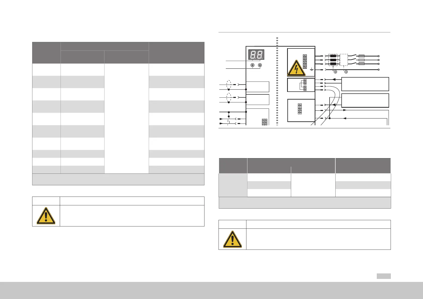
For devices of sizes Size 5 to Size 7 a mains choke is imperative. Due to a different precharging
technology in these devices, it is also to be ensured that the mains choke is installed between
the servo drive and mains lter (see Figure 4.16).
K1
FN
USB 1.1
ISD00
ISD01
ISD02
OSD02
Relay
ENPO(STO)
Motor
3
Option 2
Control
Service
interface
ISDSH(STO)
ISA00+
ISA00-
ISA01+
ISA01-
Analog setpoint 1
Analog setpoint 2
+24 V DC against
DGND
+24 V(U
H
)
3
4
5
6
10
15
16
17
9
23
24
22
RSH
Diagnosis
STO
12
11
1
2
14
13
E/A-GND
Relay
Digital2
RB-
RB+
ZK+
ZK-
Brake
resistor
U
V
W
6
8
Triggering of
motor brake
ISD03
ISD04
ISD05
18
19
20
ISD0621
OSD01
8
Digital1
OSD00
7
Digital0
GND
OSD03
2
+24 V
1
3
5
9
DC-link
OSD04
5 4321
10 9876
15 14 13 12 11
DGND
DGND
43 21
9876
~
+
-
D1, D2
T1, T2
Ethernet
L1
PE
L2
L3
L1
L2
L3
Mains three-phase
24 V DC Power supply for
control electronic (U
V
)
24 V DC Power supply
for brake (I
IN
= 2,0 A)
Communication
Field buses
Brake (+)
Brake (-)
(+)
-
+
-
+
e.g. additional
encoder
Encoder
Resolver
1
2
1
2
Top side
X11
X10
X9
X2
X3
X4
X20
X8
X7
X6
X5
X12
Service
interface
+24 V bridge only
for MSD Servo Drive
AC-AC Size 5
Figure 4.16 Connection example, control/mains supply for Size 5 to Size 6A
4.8.5 AC mains supply, Size 7
Servo drive
Device connected load
1)
[kVA]
Specied mains fuse, utilisation
class gG [A]
With mains choke (2%u
K
)
Without mains choke
G395-250
173
For devices of Size 7
mains choke
is imperative.
3xmaximum 300
G395-325
225 3xmaximum 400
G395-450
310 3xmaximum 500
1) At 3x400V mains voltage
2) Second value applies for devices with water cooling
Table 4.8 Connected load and mains fuse (Size 7)
CAUTION! Damage to the device due to incorrect operation!
• Carelessness can cause damage to the device.
For devices of sizes Size 5 to Size 7 a mains choke is imperative. Due to a different precharging
technology in these devices, it is also to be ensured that the mains choke is installed between
the servo drive and mains lter (see Figure 4.17).
 Loading...


