MSD Single-Axis System Operation Manual AC-AC Servo Drive
ID no.: CA65642-001 06/2018
moog
39
Electrical installation
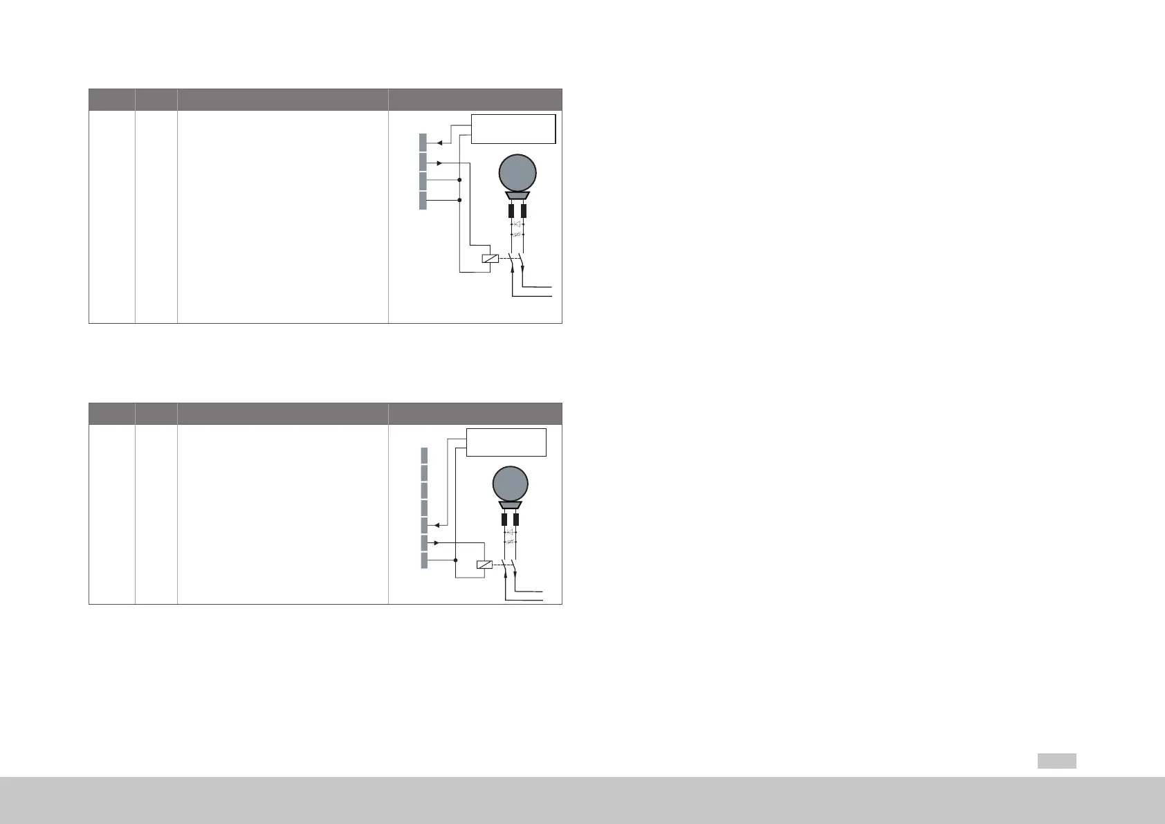
Des. Term. Specication Connection
+24 V
OSD03
GND
X20/1
X20/2
X20/3
• Short circuit proof
• External power supply
24VDC (I
IN
=2.1A) required
• For operating a motor holding brake up to
I
BR
=2.0Amaximum, for brakes with a
higher current requirement a relay must be
connected in between.
• Overcurrent causes shutdown
• Congurablecablebreakmonitoring<200mA
in state "1" (up to the relay)
M
Brake (+)
Brake (-)
+24 V DC
+24 V 1
2
GND 3
24 V DC supply
for brake (I
IN
= 2,1 A)
GND 4
Table 4.12 Specication of the terminal connections X20 (Size 5 to Size 6A)
On Size 7 the connector X44 is intended to be used to connect a motor brake.
Des. Term. Specication Connection
+24 V
OSD03
GND
X44/5
X44/6
X44/7
• Short circuit proof
• External power supply
24VDC (I
IN
=2.1A) required
• For operating a motor holding brake up to
I
BR
=2.0Amaximum, for brakes with a
higher current requirement a relay must be
connected in between
• Overcurrent causes shutdown
• Congurablecablebreakmonitoring<200mA
in state "1" (up to the relay).
X44
M
Brake (-)
+24 V DC
+24 V DC supply
for brake (I
IN
= 2 A)
+24 V 1
GND 2
VL1 3
VL2 4
+24 V 5
6
GND 7
Table 4.13 Specication of the terminal connections X44 (Size 7)
4.10 Specication, USB interface
The service and diagnostic interface X2 is designed as a USB V1.1 interface. It is only
suitable for connecting a PC for commissioning, service and diagnostics using the
software Moog DriveADministrAtor5.
Technical specication:
y USB1.1 standard - full speed device interface
y Connection via commercially available USB interface cable typeA to typeB
(see also MSDServoDrive Ordering Catalog)
4.11 Specication, Ethernet interface
The service and diagnostic interface X3 is designed as an Ethernet interface. It is only
suitable for connecting a PC for commissioning, service and diagnostics using the
software Moog DriveADministrAtor5.
Technical specication:
y Transfer rate 10/100Mbits/s BASE-T
y Transmission prole IEEE802.3 compliant
y Connection via commercially available crosslink cable
(see also MSDServoDrive Ordering Catalog)
4.12 Option 1 (Communication)
Depending on the MSDServoDrive variant, Option1 is factory-congured with various
options. Field bus options such as EtherCAT, PROFIBUS or SERCOS are available.
You will nd all available options in the MSDServoDrive Ordering Catalog. The user
manuals for the respective options provide detailed information on commissioning.
 Loading...


