MSD Single-Axis System Operation Manual AC-AC Servo Drive
ID no.: CA65642-001 06/2018
moog
45
Electrical installation
4.15.3 Switching in the motor cable
CAUTION! Damage to the device due to switching in the motor cable!
• Carelessness can cause damage to the device
Switching in the motor cable must take place with the power switched off and the power
stage disabled, as otherwise problems such as burned contactor contacts or power stage
damage may occur.
To ensure unpowered switch-on, you must make sure that the contacts on the motor
contactor are closed before the servo drive power stage is enabled. At the moment
when the contactor is switched off it is necessary for the contact to remain closed until
the servo drive's power stage is shut down and the motor current is 0. This is achieved
by using appropriate safety delays for the switching of the motor contactor in the control
sequence for your machine.
Despite these measures, the possibility cannot be ruled out that the servo drive may
malfunction during switching in the motor cable.
4.16 Braking resistor (RB)
In regenerative operation, e.g. when braking the drive, the motor feeds energy back
to the servo drive. This increases the voltage in the DC link. If the voltage exceeds
the switch-on threshold, the internal brake chopper transistor is activated and the
regenerated power is converted into heat by means of a braking resistor.
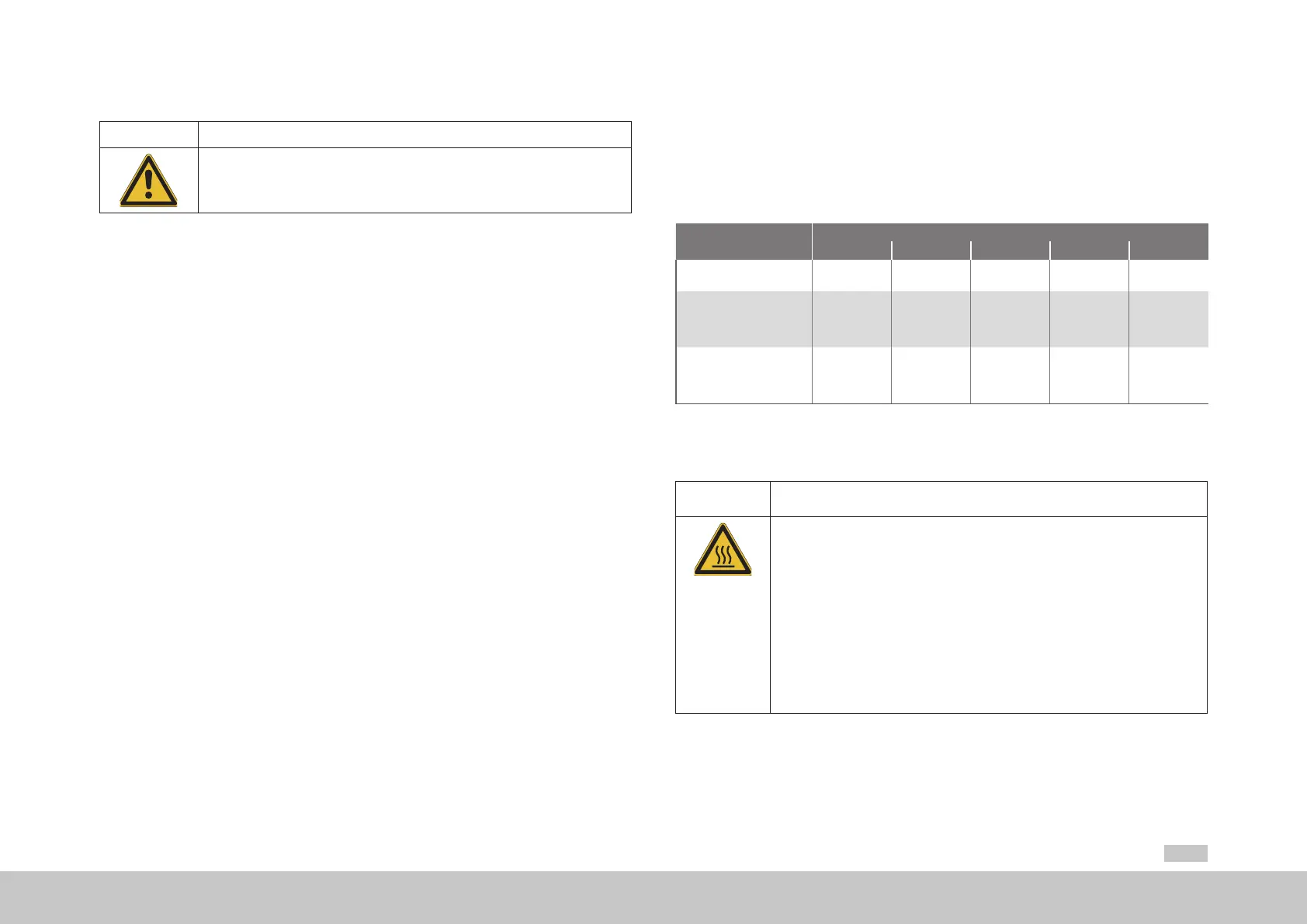
Device
Mains voltage
1x230V 3x230V 3x400V 3x460V 3x480V
G392-004A 390VDC - - - -
G392-004/G395-016
to
G392-032/G395-032
- 390VDC 650VDC 745VDC 765VDC
G392-045/G395-053
to
G392-170/G395-450
- 820VDC 820VDC 820VDC 820VDC
Table 4.20 Brake chopper switch-on thresholds (DC link voltage)
4.16.1 Protection in case of brake chopper fault
WARNING! Risk of injury due to hot surfaces caused by a faulty brake chopper!
• Carelessness may result in serious burns or damage.
If the brake chopper is overloaded the internal brake chopper transistor may be switched
on continuously, which will result in the overheating of the device and the braking resistor.
Temperatures of up to +250 °C (+482 °F) may be reached. To prevent more serious damage
we recommend the activation of the following software function:
You can activate this function by assigning BC_FAIL(56) to any digital output
(MoogDriveADministrAtor5 ►"I/O conguration" ►Digital outputs ►OSD00 to OSD02). In
the event of a fault the selected output then switches from 24 V to 0 V.
With this signal it is to be ensured that the servo drive is safely disconnected from the mains
supply and the power stage is disconnected. For a multi-axis group, deactivate all power
stages.
 Loading...


