18
Mechanical installation
MSD Single-Axis System Operation Manual AC-AC Servo Drive
ID no.: CA65642-001 06/2018
moog
3.4 Dimensions, devices with liquid cooling
MSD
ServoDrive
AC-AC
Size 3 Size 4 Size 5 Size 6 Size 6A Size 7
G395-016
G395-020
G395-024
G395-032
G395-053
G395-070
G395-084
G395-110
G395-143
G305-170
G395-210
G395-250
G395-325
G395-450
Weight [kg]
6.5 7.5 16.5 31.5 41.1
100
B (width) 130 171 190 280 380
H (height)
1)
295 345 540 855
T (depth)
1)
224 198 202 282 287
A
80 120 148 200
150
A1
10 25 39 65
29
A2 60 70
C 382 378 581 952
C1
5 8 10
14
H1 392 394 600 979/995
4)
H2
38.5 16.5 20
62
H3
75 70 53.5 56.5
124
T1
74 74
DØ 4.8 7 9.5 12
Screws 4xM4 4xM6 4xM8 6xM10
S 3/8 inch (female thread)
D1Ø 48 (bore for pipe tting)
E 2
F
2)
≥150 ≥180
G
2)
≥270 ≥300 ≥500
All dimensions in mm
1) Without terminals, connectors and shield plates
2) If necessary take into account larger bending radii for connection cables.
3) Without/with terminal covers and shield plates
4) Without/with busbars
Table 3.3 Dimensions, housing with liquid cooling, see Figure3.3 to Figure3.5
NOTE:
The minimum distance "E" specied in the table applies for devices of the
same power rating. On butt mounting devices with different drive powers, you
should arrange the devices in order by power rating (e.g., viewed from the
left, Size 4-Size 3-Size 2-Size 1). This arrangement will minimise the thermal
interaction.
On butt mounting MSDServoDrives with other devices, you should ensure
there is no thermal interaction between the devices.
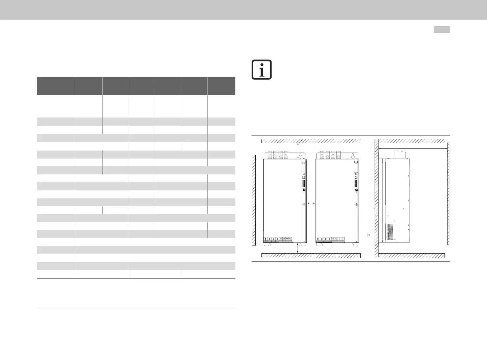
3.4.1 Mounting clearances
E
G
F
F
Figure 3.3 Mounting clearances for liquid cooling, schematic depiction for Size 3 to Size 7
 Loading...


