72
MSD Single-Axis System Operation Manual AC-AC Servo Drive
ID no.: CA65642-001 06/2018
moog
A.2 Technical data, MSDServoDrive
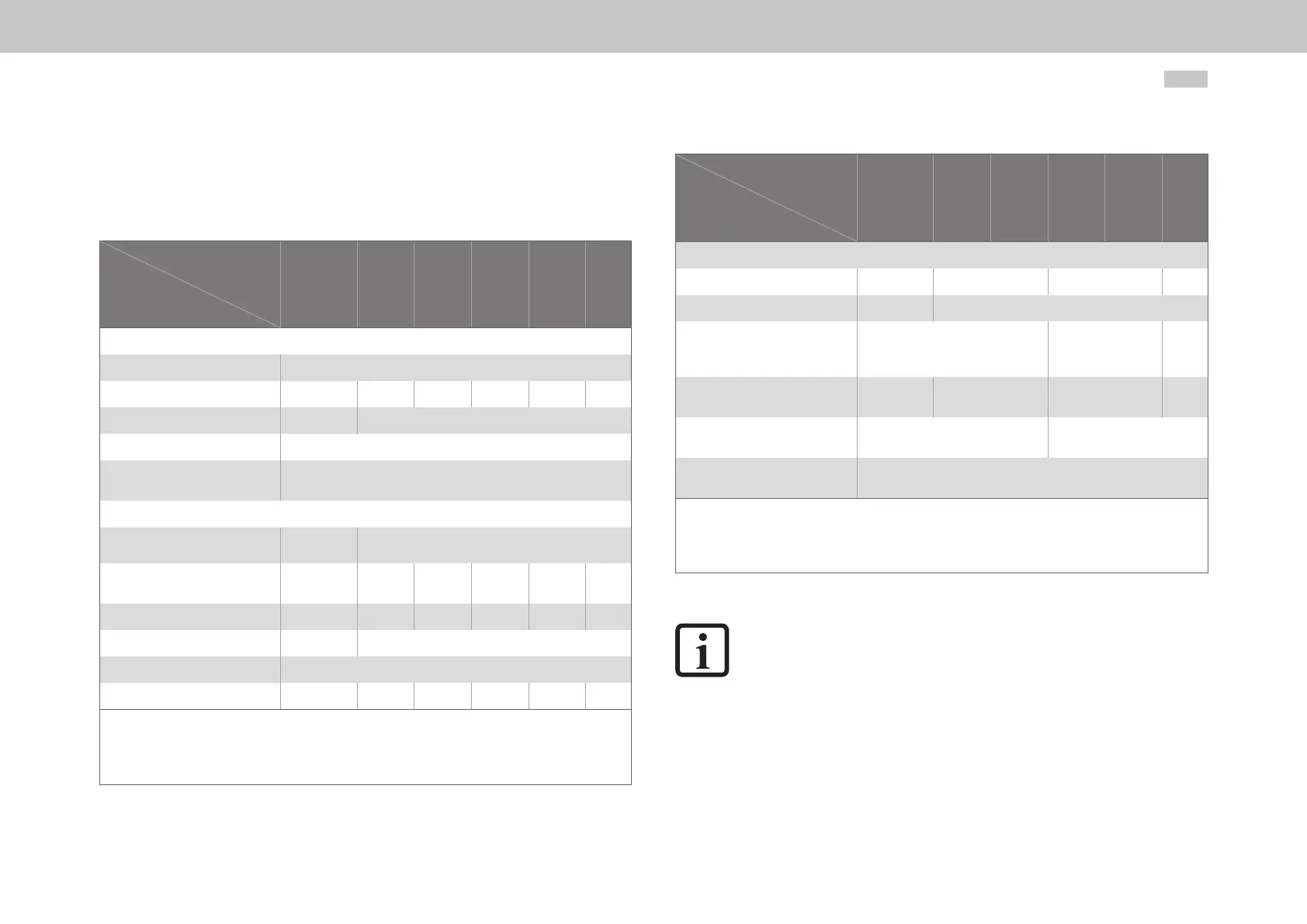
A.2.1 G392-004A to G392-016, air cooling
Designation
Technical data
G392-004A
G392-004
G392-006
G392-008
G392-012
G392-016
Output, motor side
1)
Voltage
4)
3-phase U
Mains
Rated current, effective (l
N
) 4A 4A 6A 8A 12A 16A
Peak current See A.1.1 See A.1.2
Rotating eld frequency 0 ... 400Hz
Switching frequency of the power
stage
4, 8, 12, 16kHz
Input, mains side
Mains voltage
1x 230V
±10%
(3x230V/ 3x400V/ 3x460V/ 3x480V) ±10%
Device connected load
1)
(with mains choke)
2.2kVA 2.9kVA 4.4kVA 6kVA 9.1kVA 12kVA
Current
1)
(with mains choke) 9.5A
2)
4.2A 6.4A 8.7A 13.1A 17.3A
Asymmetry of mains voltage - ±3%maximum
Frequency
50/60Hz ±10%
Power dissipation at I
N
1)
85W 96W 122W 175W 240W 330W
1) Data referred to mains voltage 3x400V
eff
(for G392-004A: 1x230Veff) and switching frequency of power stage 8kHz
2) Without mains choke
3) Connection of an ext. braking resistor to devices with int. braking resistor not permitted (model G392-xxx-xxx-xx2/xx4)!
4) When designing the drive, it is to be taken into account that the maximum output voltage reduces as a function of the active power.
Table A.9 Technical data, G392-004A to G392-016, air cooling
Designation
Technical data
G392-004A
G392-004
G392-006
G392-008
G392-012
G392-016
DC link
Capacitance 1740µF 400µF 725µF 1230µF
Brake chopper switch-on threshold
1)
390VDC 650VDC
Minimum ohmic resistance of an
externally installed braking resistor
3)
72Ω 39Ω 20Ω
Brake chopper peak power
with external braking resistor
1)
2.1kW 5.9kW 11kW 21kW
Optional:
Internal braking resistor
PTC (175Ω) 90Ω
Brake chopper peak power
with internal braking resistor
See “Table 4.21 Data on the integrated braking resistor (model G392-xxx-xxx-
xx2/xx4 and G395-xxx-xxx-xx2/xx4)”
1) Data referred to mains voltage 3x400V
eff
(for G392-004A: 1x230Veff) and switching frequency of power stage 8kHz
2) Without mains choke
3) Connection of an ext. braking resistor to devices with int. braking resistor not permitted (model G392-xxx-xxx-xx2/xx4)!
4) When designing the drive, it is to be taken into account that the maximum output voltage reduces as a function of the active power.
Table A.9 Technical data, G392-004A to G392-016, air cooling
NOTE:
You will nd more information on the brake chopper switch-on threshold in
chapter “4.6 Connection of PE conductor”
 Loading...


