30
Electrical installation
MSD Single-Axis System Operation Manual AC-AC Servo Drive
ID no.: CA65642-001 06/2018
moog
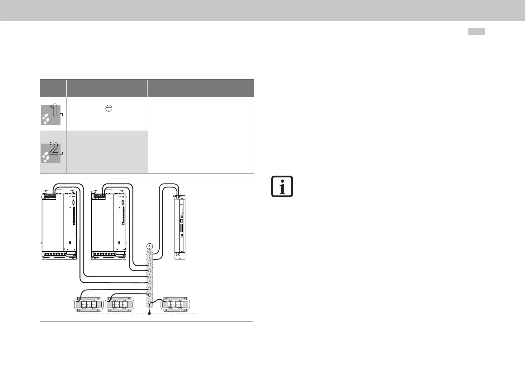
4.6 Connection of PE conductor
Step Action
PE mains connection
according to IEC/EN61800-5-1
Earth each of the servo drives!
Connect the terminal in a star
conguration and with a large area
connection to the PE rail (main earth)
in the switch cabinet.
As the leakage current >3.5mA, the following applies to
the PE connection:
•Mainsconnection<10mm
2
(0.015 in
2
) copper:
protective earth conductor cross-section min. 10mm²
(0.015 in
2
) copper or two wires with the cross-section of
the mains power cables (Size 1to Size 4).
•Mainsconnection≥10mm²(0.015in
2
) copper:
protective earth conductor cross-section to suit the
cross-section of the mains power cables (for Size 5 to
Size 7).
Also comply with local and national regulations and
conditions for equipment with high leakage current.
Also connect the PE conductor
connections on all other components,
such as mains choke, lter, etc. in a star
conguration and with a large area
connection to the PE rail (main earth)
in the switch cabinet.
W1
V2
W2
U2
U1
V1
W1
V2
W2
U2
U1
V1
W1
V2
W2
U2
U1
V1
PE
Figure 4.11 Star conguration layout for the PE conductor
4.7 Electrical isolation concept
The control electronics, with their logic (µP), the encoder terminals and the inputs and
outputs, are electrically isolated from the power section (power supply/DC link). All
control terminals are designed as safety extra low voltage/protective extra low voltage
(SELV/PELV) circuits and must only be operated with such SELV/PELV voltages, as per
the relevant specication. This provides reliable protection against electric shock on the
control side.
A separate control supply, compliant with the requirements of a SELV/PELV, is therefore
needed.
The overview opposite shows the potential references for the individual connections in
detail.
This concept also delivers higher operational safety and reliability of the servo drive.
NOTE:
The terminal X5 (PTC for the motor) represents a special case in relation to
insulation and isolation. On this topic follow the instructions in chapter4.15.
SELV = Safety Extra Low Voltage
PELV = Protective Extra Low Voltage
 Loading...


