moog
MSD Servo Drive Compact Operation Manual
17
[ Installation ]
to the glossaryto the table of contents
Id no.: CA97555-001, Rev. 3.0 - Date: 0 6/2012
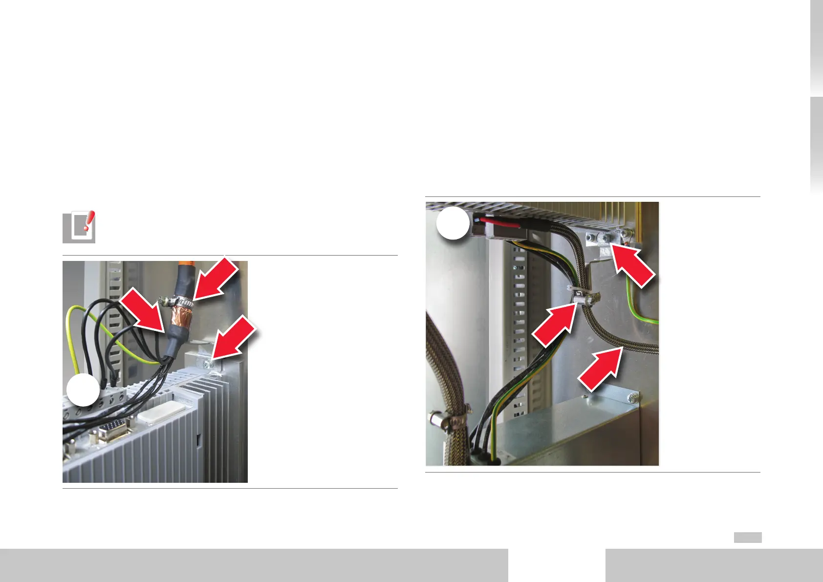
Detail1: Motor cable
At the motor connection (X1) of the MSDServoDriveCompact note the following
points:
• Secure one of the two supplied shield connection plates by the screw to the
mount on the top of the unit. Ensure the plate contacts across a wide area with
the heat sink of the MSDServoDriveCompact and with the backing plate. Use a
toothed ring.
• Strip back the shield of the motor cable on the motor connection (X1) of the
MSDServoDriveCompact as little as absolutely necessary.
• Connect the motor cable shield across a wide area to the shield connection plate
by the clamp supplied.
NOTE: Ready made-up motor cables are available for Moog servo motors. For
details refer to the Servo motors Ordering Catalog.
Fig. 3.4 Specimen setup - Detail 1: Motor cable
X1
Detail2: Control supply (+24VDC)
At the control supply connection (X2):
• Secure the second of the two supplied shield connection plates by the screw to
the mount on the bottom of the unit. Ensure the plate contacts across a wide area
with the heat sink of the MSDServoDriveCompact and with the backing plate.
Use a toothed ring.
• Slot a shield tube over the control supply cable and strip it back only as short as
necessary before the control supply connection (X2).
• Connect the shielding tube of the control supply cable across a wide area to the
shield connection plate by the clamp supplied.
Fig. 3.5 Specimen setup - Detail 2: Control supply
X2