38
CONTROL VOLTAGE OVERVIEW
Control voltages are signals used to modify circuits in an analog synthesizer. They can affect the
pitch of a VCO, the timbre produced at the output of a VCF, or the loudness at the output of a VCA.
A simple example is the VCO FREQUENCY control. It generates a voltage based on its rotation that is
connected to the control input of the VCO. When you turn it counterclockwise, the voltage and VCO
pitch are reduced. When you turn it clockwise, the voltage and VCO pitch are increased. In a xed
position, the voltage and VCO pitch remain steady.
Another example is using an LFO to modulate the pitch of a VCO. The LFO produces a control voltage
that is applied to the VCO control input. This causes the VCO pitch to go up and down at the rate of
the LFO.
In terms of analog synthesizers, audio signals are used to generate sound, typically in the audible
range of 20Hz to 20kHz. Control signals are used to modify the audio signals. NOTE: In analog
synthesizers, audio signals can also be used as control signals. Timing signals are signals that change
rapidly in time, such as a gate signal. Frequently they have only two levels that represent On and Off.
A Gate signal in the Mother-32 for instance, is off at 0 Volts and on at +5 Volts. A Gate signal can be
used to trigger events, such as starting an Envelope Generator, or starting the sequencer running.
In a fully modular synthesizer, all connections must be made with patch cables. The Mother-32 is a
semi-modular synthesizer. This means that some connections have been made internally so that patch
cables are not required to produce sound at the output or to perform basic useful modulation. For
each synthesizer function there are control inputs and outputs that appear on the patchbay.
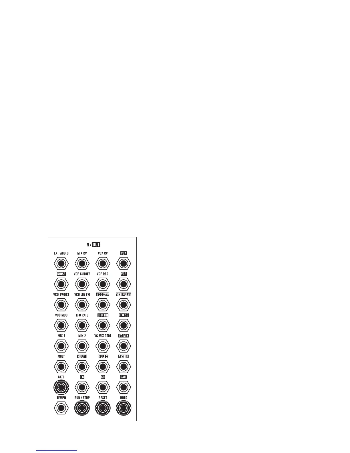
MOTHER-32 PATCHBAY
The Mother-32 Patchbay contains 32 x 3.5mm patch points,
which allow for extended synthesis capabilities and modular
interconnectivity.
The Mother-32 Patchbay is designed to work with 3.5mm
patch cables only. A pack of 5 is included with your Mother-32.
If you should need more, 6” and 12” packs of Moog cables are
available for purchase at authorized dealers.
Patch points whose labels are written in standard text are inputs,
while patch points whose labels are reversed are outputs.
Patch points with circles around them are Gate inputs.
NOTE: When patching, it is OK to split an output signal with a
“Mult”, a “y” cable, or with cables with stackable plugs. When
connecting to inputs, only connect one output signal to a single
input to prevent over-voltages.

 Loading...