____________________________________________________________________
_______________________________________________________________________
MN0090-05 Page 19 of 68 18008
MPT-90 PRODUCT MANUAL This document contains U.S. export controlled technical data as regulated by the U.S. Export Administration Regulations 15 CFR Parts 730-774, export, disclosure or transfer contrary to U.S. law is prohibited.
3.1.4 General Purpose I/O Pass Through & Chassis Ground All Models
User supplied power to payloads. 8A max.
User supplied power to payloads. 8A max.
User supplied power to payloads. 8A max.
User supplied power to payloads. 8A max.
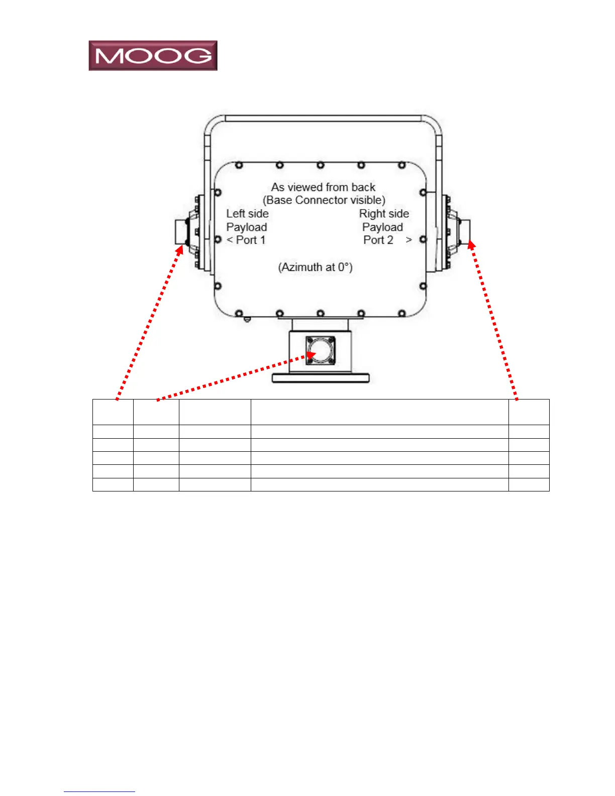
The General Purpose I/O conductors are typically used for powering devices connected
to Port 1 and/or Port 2. The conductor connected to pins 46 are twisted together with the
conductor connected to pins 49, likewise 47 & 48 are paired. These are conductors
through the slip ring on continuous models, allowing high current (up to 8A continuously)
connections to the payload. Both left and right side ports are connected to the base
allowing a single user supplied power supply to power loads on both sides, assuming
they are of the same voltage. The maximum continuous current rating through the slip
ring is 8 amps, meaning the sum of both the left and right side through any one conductor
is not to exceed 8A. The slip ring is rated up to 210VDC, and may be used for AC current
with a 500 VRMS dielectric strength in all combinations. Chassis Ground is internally
connected to the mechanical chassis of the positioner, and is available on all three
connectors. Chassis ground is not internally connected to any of the General Purpose
I/O ports, but may be connected externally if desired.