____________________________________________________________________
_______________________________________________________________________
MN0090-05 Page 20 of 68 18008
MPT-90 PRODUCT MANUAL This document contains U.S. export controlled technical data as regulated by the U.S. Export Administration Regulations 15 CFR Parts 730-774, export, disclosure or transfer contrary to U.S. law is prohibited.
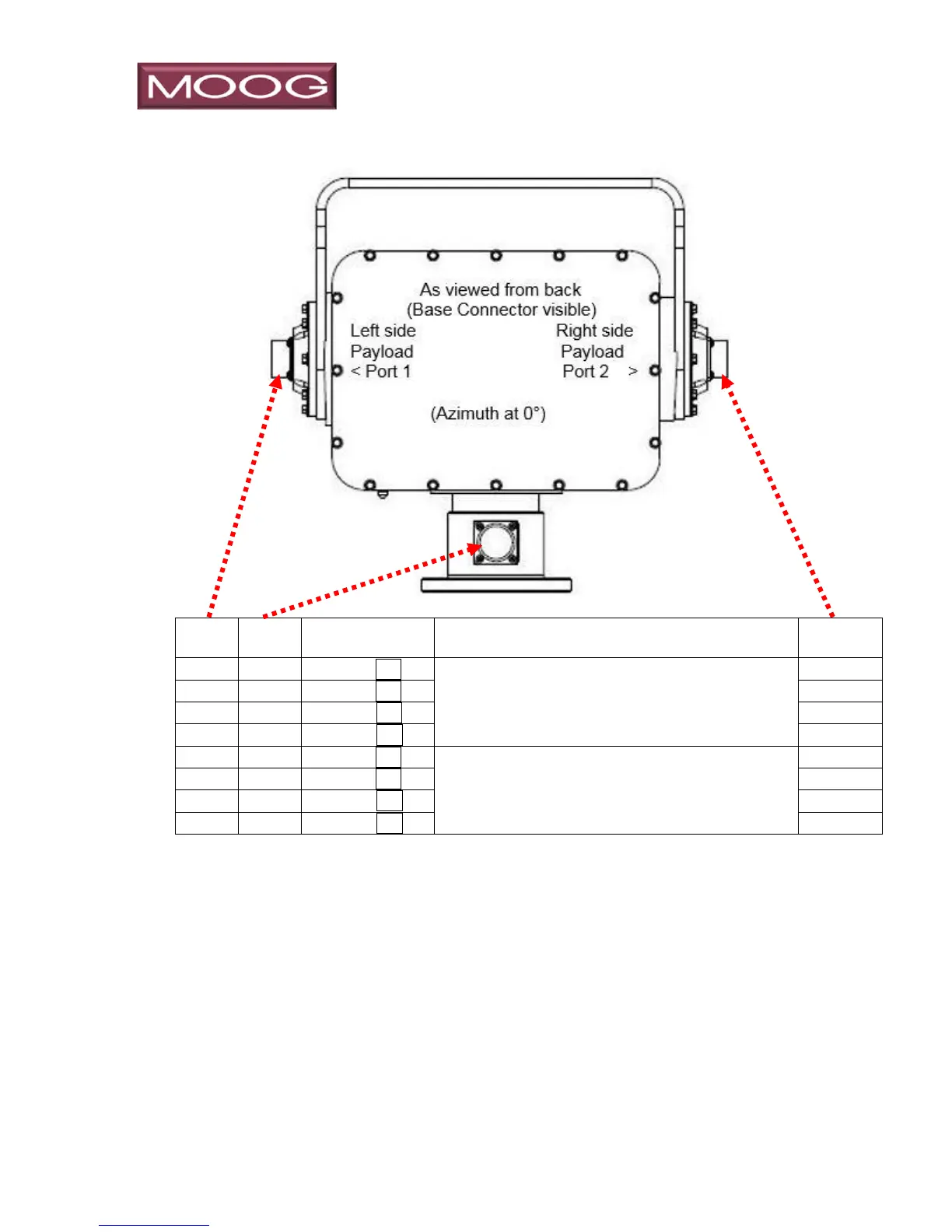
3.1.5 Model 8-PB133, 10/100 Ethernet Ports 1 & 2
Ethernet User 10/100 “A” to port 1
Ethernet User 10/100 “C” to port 2
Typical 10/100 Ethernet connections require 2 sets of Twisted Pair (TP) conductors,
4 conductors total. Gig-E Ethernet connections require 4 sets of TP, a total of 8
conductors. Due to limitations of the conductor availability in the slip ring, the MPT
series allocates 8 conductors between the base connector and the payload ports.
Therefore, these conductors may be configured as two 10/100 Ethernet ports, one
to each side (Model 8-PB133 depicted above) or as a single Gig-E signal path to
either side (See next two pages).
Colors shown for IP signals per EIA/TIA 568B are to aid or reference external wiring
to the ports and do not represent actual color of conductors inside the positioner.