____________________________________________________________________
_______________________________________________________________________
MN0090-05 Page 32 of 68 18008
MPT-90 PRODUCT MANUAL This document contains U.S. export controlled technical data as regulated by the U.S. Export Administration Regulations 15 CFR Parts 730-774, export, disclosure or transfer contrary to U.S. law is prohibited.
3.3 PCB Switch Settings
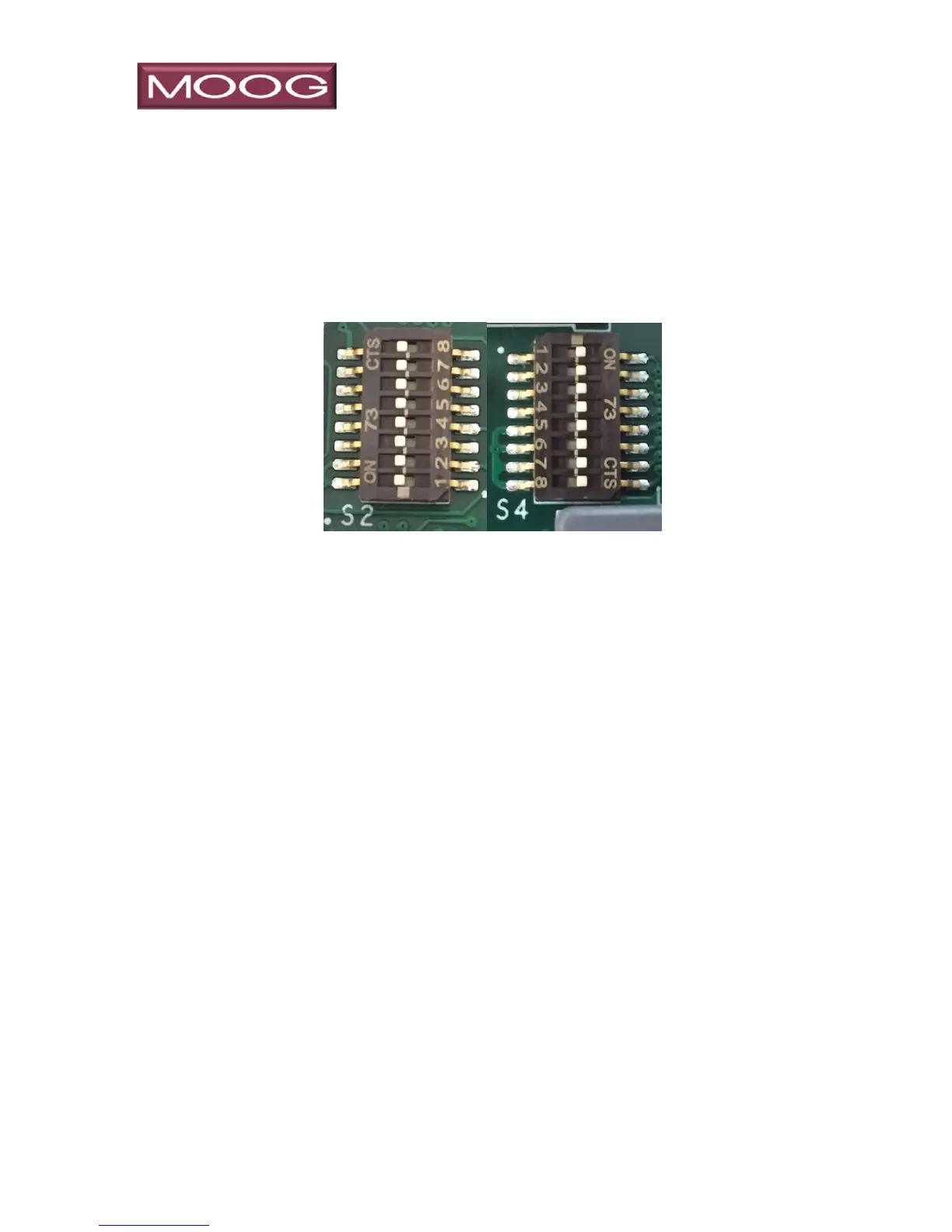
The PCB has two user configurable eight position switches (Figure 11, S2,
S4) used to configure the serial communication ports. These ports are
typically used to control the positioner, or the payloads attached to the
positioner.
Figure 11: PCB Switches
3.3.1 S2 switch settings for serial communication ports
S2 configures the user control serial ports on the base and payload ports. Set
for the desired serial communication mode. Note that in RS485 mode,
termination should be ON for the last unit in the chain.
BASE PAYLOAD PAYLOAD
CONNECTOR PORT 1 PORT2
RS422 RS232 PINS PINS PINS
Serial Tx+ (TXD) 10 16 16
Serial Tx- 33 38 38
Serial Rx+ (RXD) 11 17 17
Serial Rx- 34 39 39
Signal Ground (Gnd) 12 18 18