____________________________________________________________________
_______________________________________________________________________
MN0090-05 Page 26 of 68 18008
MPT-90 PRODUCT MANUAL This document contains U.S. export controlled technical data as regulated by the U.S. Export Administration Regulations 15 CFR Parts 730-774, export, disclosure or transfer contrary to U.S. law is prohibited.
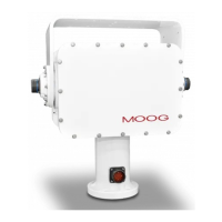
Figure 6: Accessing the Circuit Board
2. Loosen the two #1 Philips head screws at the top of the board; these screws
are retained with a small O-Ring between the PCB and the bracket; turn only
enough to release the bracket. You may need to pull the bracket outward to
allow the board to swing downward. Refer to Figure 7 below.
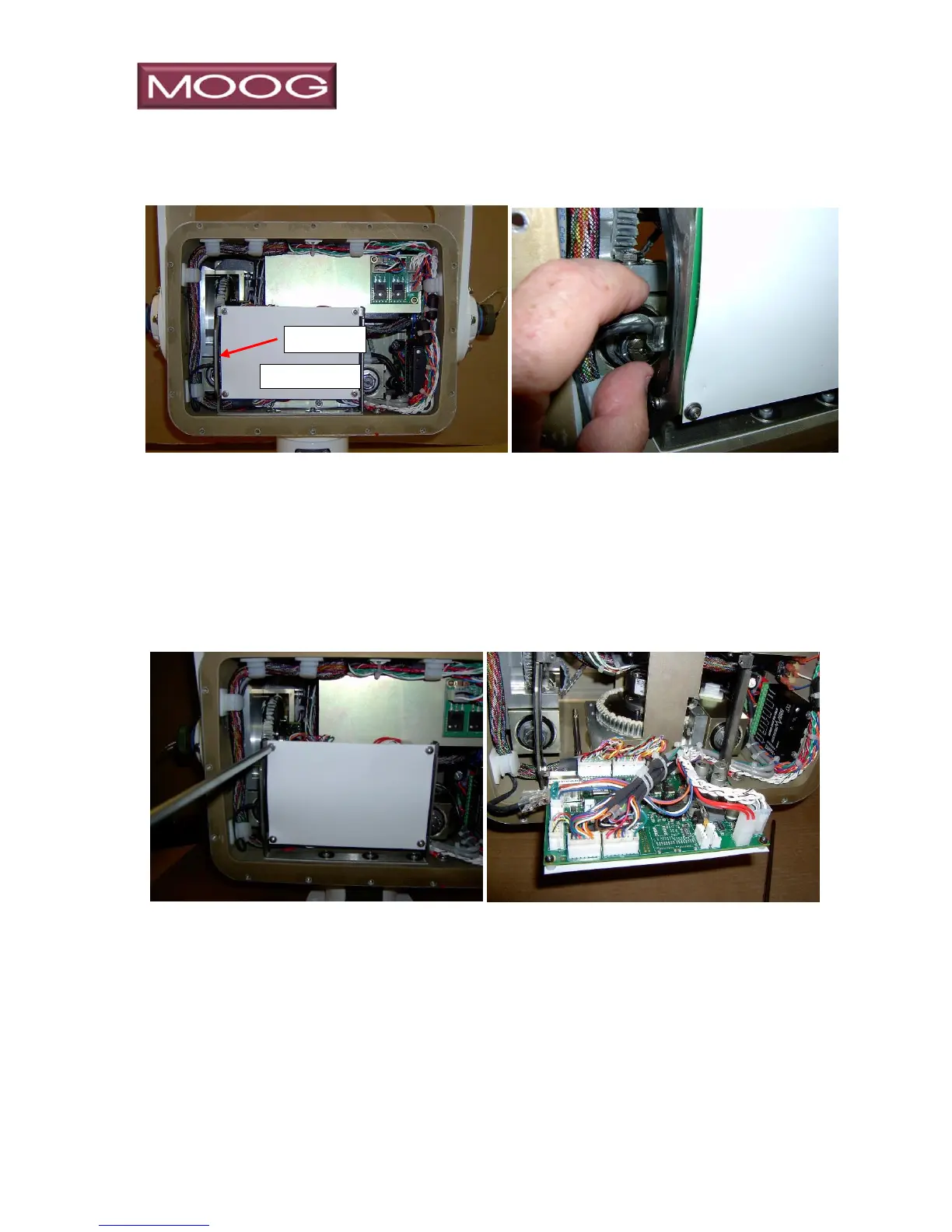
Figure 7: Circuit Board
3. The PCB has multiple switches and jumpers providing options that are used
for customer configuration. The options are:
Setting input voltage range
Communication settings for primary control of the MPT-90
Communication settings for secondary control of the MPT-90
Communication settings for Payload control
Voltage settings for Port Payload power
Voltage and high-side/low-side switching of Auxiliary Port power
Refer to Figures 7 and 8.