____________________________________________________________________
_______________________________________________________________________
MN0090-05 Page 29 of 68 18008
MPT-90 PRODUCT MANUAL This document contains U.S. export controlled technical data as regulated by the U.S. Export Administration Regulations 15 CFR Parts 730-774, export, disclosure or transfer contrary to U.S. law is prohibited.
3.2.1.2 PBC Jumper Settings:
NOTE
All jumper settings, the screened dot is Pin 1. Refer to Figure 10 below.
3.2.1.2.1 P1 Input Power:
The positioner requires 24 to 28 VDC to operate, with positive current applied
to pins 45 & 52 and power return through pins 50 & 51 of the base connector.
Note that due to current limitations of the pins in the base connector, the user
must apply power to both pairs of pins to assure proper operation. In the event
that two separate power supplies are used, you must connect the two negative
wires (pins 50 & 51) together.
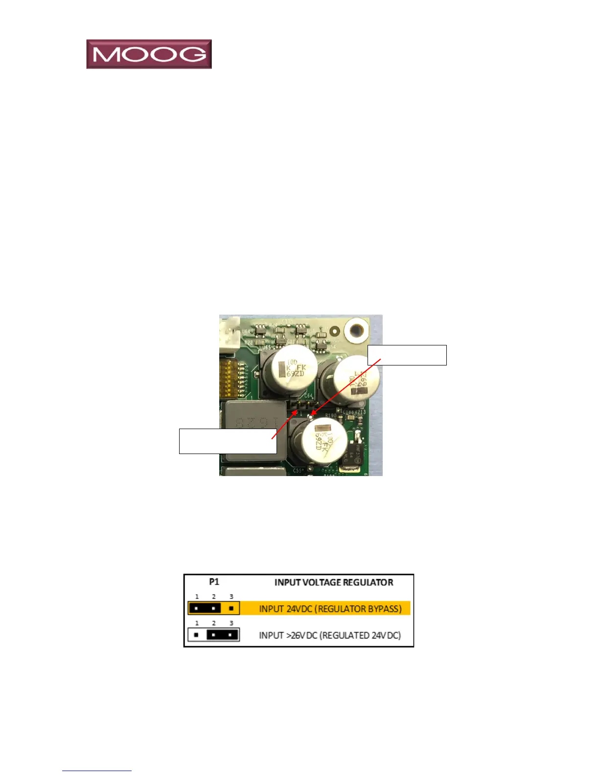
Figure 10: Jumper Locations
The MPT product may be configured to operate on 28-70 VDC by changing
the PCB P1 jumper setting. To reconfigure to operation on voltages higher
than 28 VDC, you must move the jumper on P1 (located in the upper right
corner of the Moog Controller PCB) from the default position of 1-2 to the 2-3
position. The dot screened on the PCB indicates pin 1.
NOTE
The 24 VDC is passed to the payload ports, and is not regulated if the input
power is in the default configuration. If the P&T is configured for higher
voltage usage, the 24 VDC payload power is regulated.
Jumper P1, shown
without jumper for clarity