____________________________________________________________________
_______________________________________________________________________
MN0090-05 Page 30 of 68 18008
MPT-90 PRODUCT MANUAL This document contains U.S. export controlled technical data as regulated by the U.S. Export Administration Regulations 15 CFR Parts 730-774, export, disclosure or transfer contrary to U.S. law is prohibited.
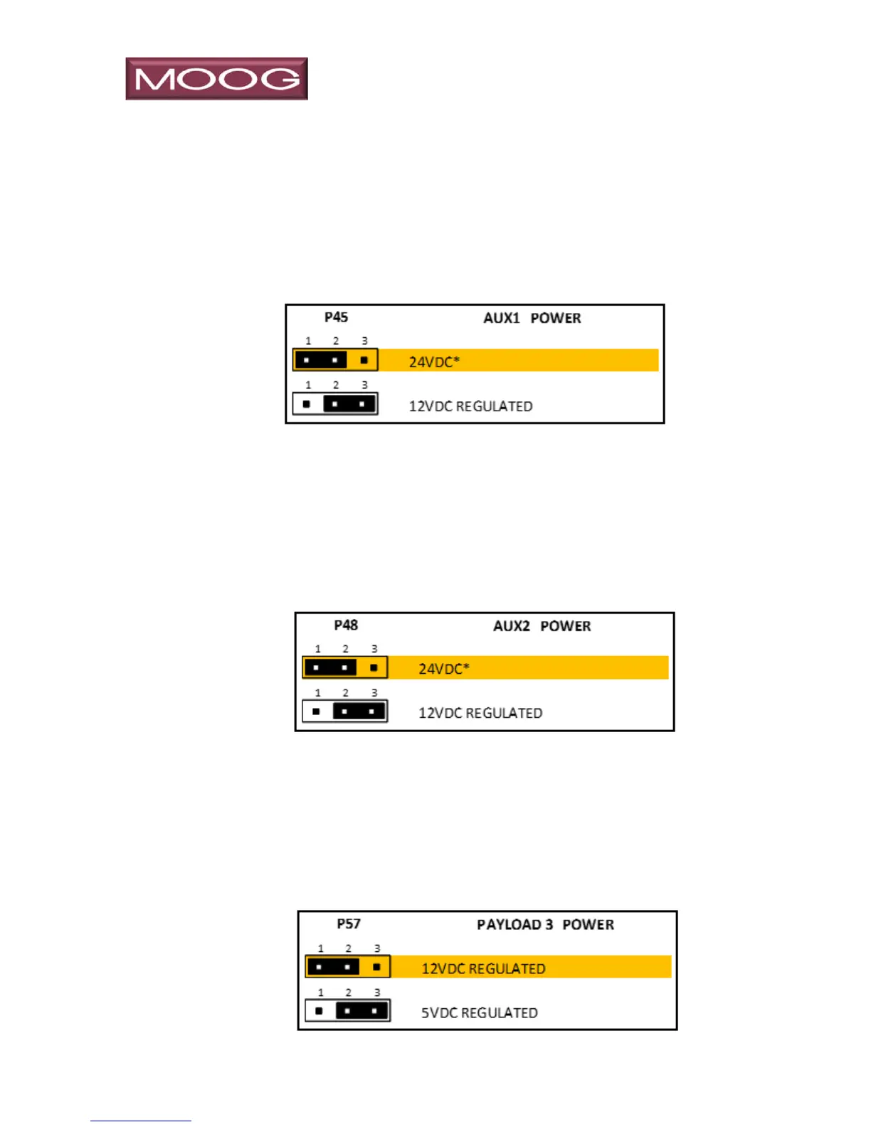
3.2.1.2.2 P45
P45 is used to select the voltage available on “Aux1 Power” (pin 36 on
Payload Port 1). In the default mode with the jumper on pins 1-2, pin 36 of
Payload Port 1 will have the P&T source voltage (*typically +24 VDC)
available with respect to pin 14. Moving the jumper to pins 2-3 will reduce
this to +12 VDC regulated.
3.2.1.2.3 P48
P48 is used to select the voltage available on “Aux2 Power” (pin 37 on
Payload Port 1). In the default mode with the jumper on pins 1-2, pin 37 of
Payload Port 1 will have the P&T source voltage (*typically +24 VDC)
available with respect to pin 15. Moving the jumper to pins 2-3 will reduce
this to +12 VDC regulated.
3.2.1.2.4 P57
P57 is used to select the voltage available on “Payload 3 (pin 45 of Payload
Port 1). In the default mode with the jumper on pins 1-2, pin 45 of Payload
Port 1 will have +12 VDC regulated power available with respect to pin 50.
Moving the jumper to pins 2-3 will reduce this to +5 VDC regulated.