____________________________________________________________________
_______________________________________________________________________
MN0090-05 Page 21 of 68 18008
MPT-90 PRODUCT MANUAL This document contains U.S. export controlled technical data as regulated by the U.S. Export Administration Regulations 15 CFR Parts 730-774, export, disclosure or transfer contrary to U.S. law is prohibited.
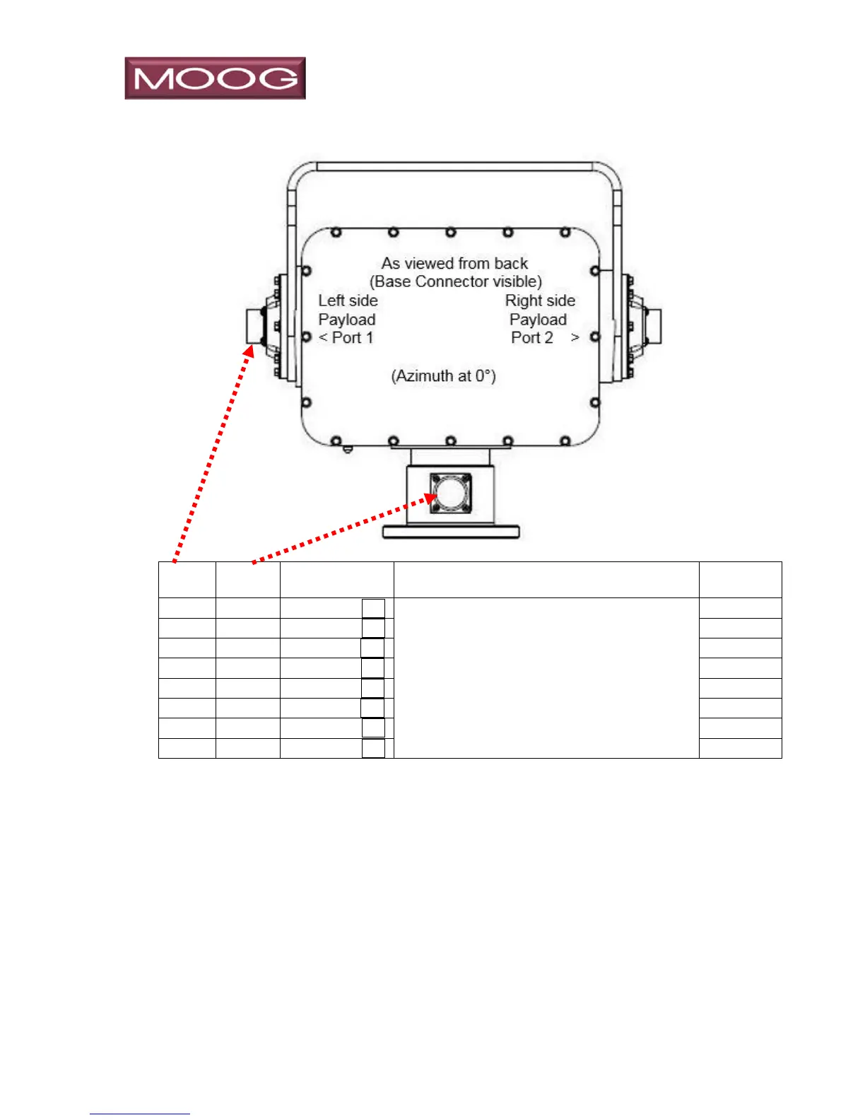
3.1.6 Model 8-PB151, Gigabit Ethernet Base to Port 1 Payload
Ethernet User GigE Base to port 1
Gig-E Ethernet connections require 4 sets of TP, a total of 8 conductors, so in this
configuration there is a single GigE provision wired to Port 1.
Colors shown for IP signals per EIA/TIA 568B are to aid or reference external wiring
to the ports and do not represent actual color of conductors inside the positioner.