____________________________________________________________________
_______________________________________________________________________
MN0090-05 Page 7 of 68 18008
MPT-90 PRODUCT MANUAL This document contains U.S. export controlled technical data as regulated by the U.S. Export Administration Regulations 15 CFR Parts 730-774, export, disclosure or transfer contrary to U.S. law is prohibited.
1.3 DEFINITIONS, ABBREVIATIONS AND ACRONYMS
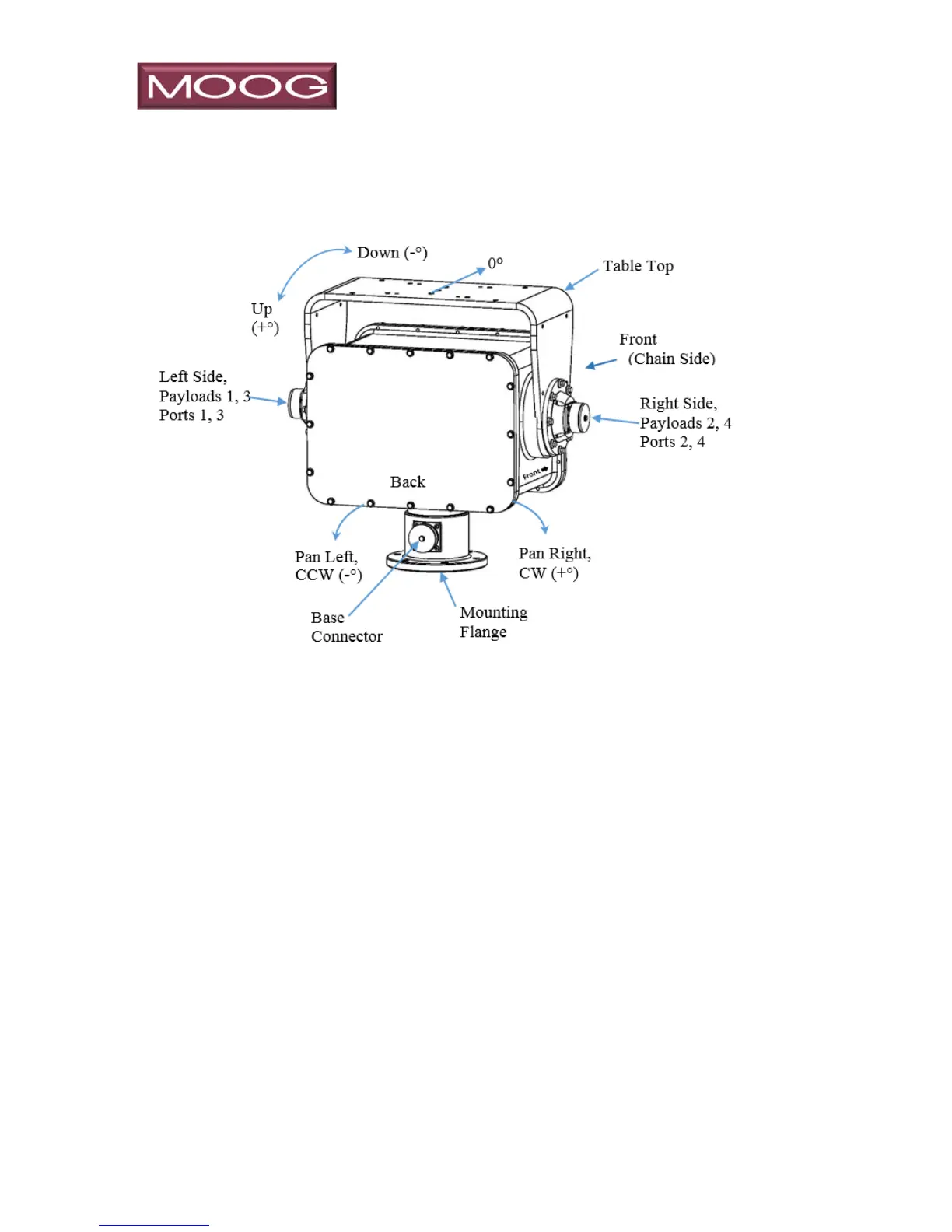
Figure 2: MPT-90 Definitions
Front: the front of the P&T is the side with the Chain Drive under the cover. Most
Moog P&T units have a label on the left side (although shown on right side in
the depiction above) pointing toward the front. Refer to Figure 2.
Zero (0°) Azimuth: typically, the center of azimuth rotation on non-continuous units,
“0° Azimuth” is when the base connector is orientated opposite of the chain
side. When positioned at 0° a cable connected to the base connector would
egress out the “back” of the unit, 180° away from the front.
Left & Right – the left and right side are considered from the perspective of a camera.
With a camera mounted toward the front, an observed video image would
providing the perspective: to “Pan Left”, you would move the positioner
Counter Clock Wise (CCW) as viewed from the top. Moving to the right or
CW increments the degree heading while moving to the left or CCW will
decrement the heading in degrees.
Up & Down – moving upward means the table top is moving toward the rear of the
unit and the indicated position would increment as the elevation increases.
Moving downward would decrement the position in degrees.