EasyManua.ls Logo

Motion iWMC Series - Chapter2 System Interfaces and Wiring; Iwmc Servo Wheel Wiring Diagram; Iwmc Wiring Diagram; Brake Resistor and Fuse Specifications

Motion iWMC Series
56 pages
Print Icon
To Next Page IconTo Next Page
To Previous Page IconTo Previous Page
Loading...
Moon Control Products Ltd. Tel.: +44 (0)1202 599922 www.mooncontrolproducts.com Page | 5
Chapter2 System Interfaces And Wiring
2.1 iWMC Servo Wheel Wiring Diagram
2.1.1 iWMC Wiring Diagram
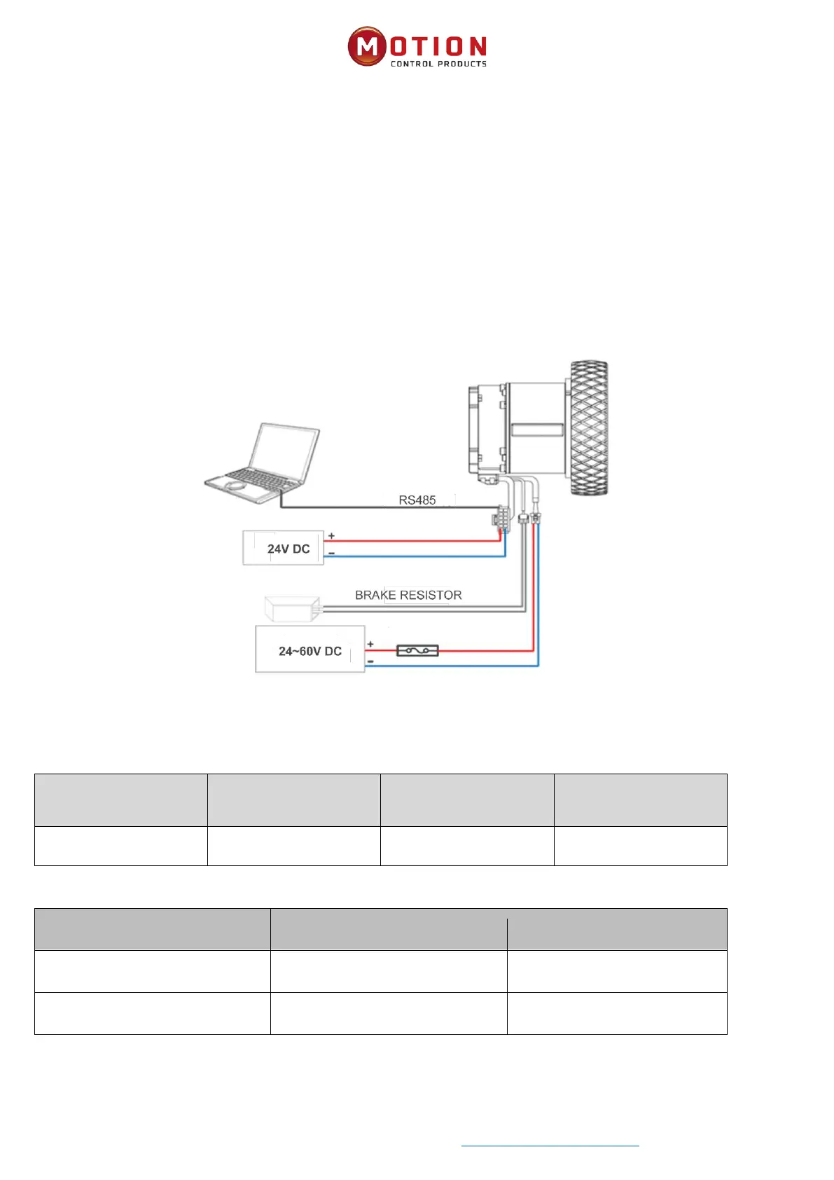
The servo wheel operates with two separate power sources: a 24V logic power supply (connected to pins 1 and 2 of the
12-pin terminal) and a 48V power supply (connected to the 2-pin power terminals) . To ensure proper operaon, the servo
wheel must be connected to both of these power supplies.
Diagram 2-1 External wiring diagram of servo wheel motor
2.1.2 Brake Resistor And Fuse Specicaons
Table 2-1 Brake resistance reference specicaons
Brake resistor model
Brake resistance value
[Ω]
Braking resistance power
[W]
Brake resistance voltage
[VDC]
T-10R-100
10
100
500
Table 2-2 Fuse reference specicaons
Model
Drive power (W)
Fuse specicaons
iWMC10409 integrated servo wheel
500
20A/58VDC
iWMC10415 integrated servo wheel
1050
90A/58VDC

Table of Contents