Moon Control Products Ltd. Tel.: +44 (0)1202 599922 www.mooncontrolproducts.com Page | 17
Driver enabling
1: Controlword=Din_Controlword (2020.0F)
0: Controlword = 0x06
The bit (bit7) of the reset fault in the control word = 1
Operaon mode selecon
1: Operang Mode = Operang Mode Selecon 1 (2020.0E)
0: Operang Mode = Operang Mode Selecon 0 (2020.0D)
Posive/negave limit switch, normally OFF, Din eecve input = 0 indicates that the
motor has reached the limit posion
Inverts command direcon in the velocity and torque mode
Sets the controlword to start quick stop. Aer quick stop, the controlword needs to be set
to 0x06 before 0x0F for enabling (if the enable funcon is congured in Din, just re-
enable it)
Acvates the posion command, for example the control word changes from 0x2F to
0x3F
For safety reasons, Pre_Enable can serve as a signal for indicang whether or not the
enre system is ready.
1: driver can be enabled
0: driver cannot be enabled
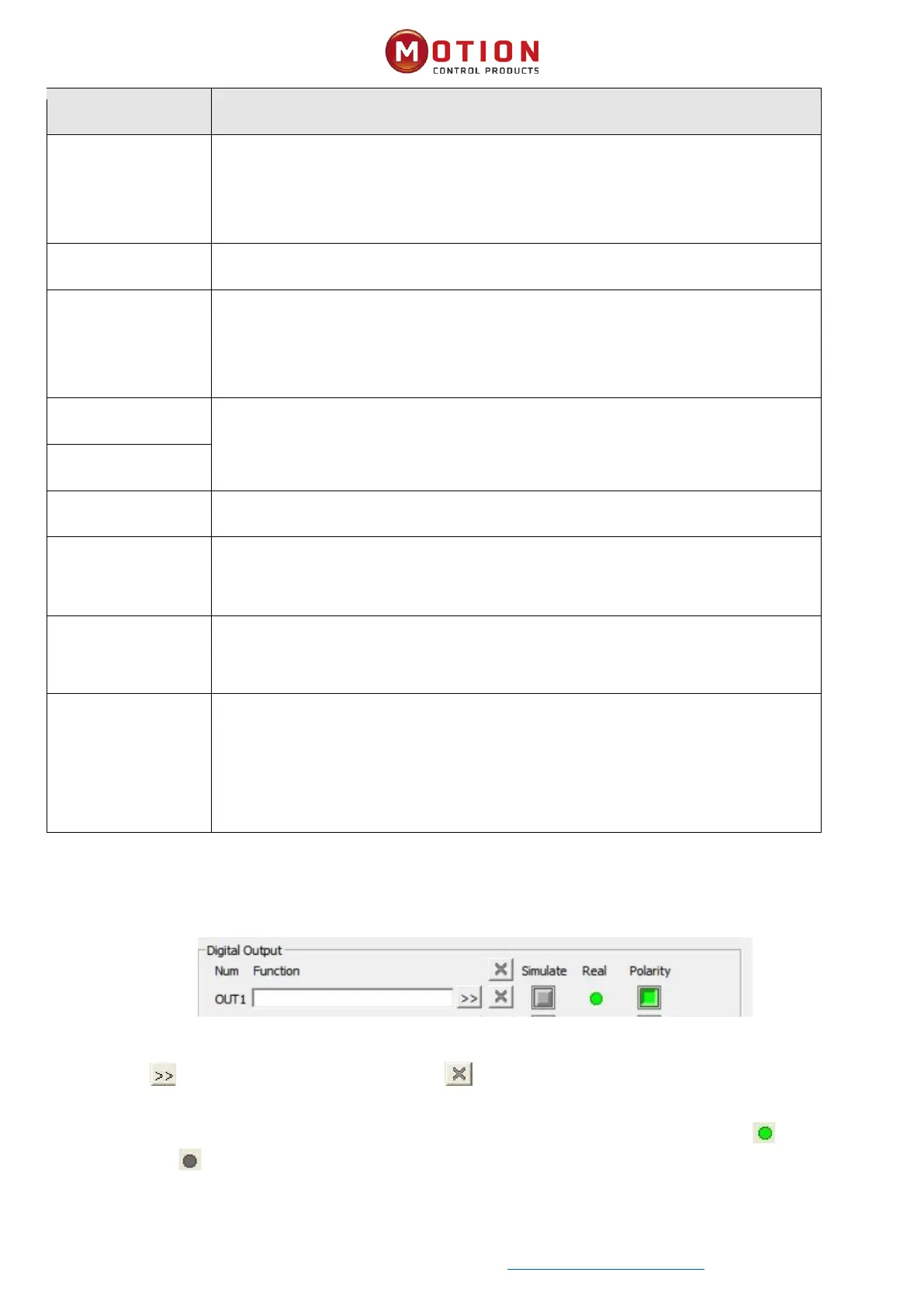
3.6.2 Digital Output
Figure 3-10 digital output
Funcon: Click to select the OUT funcon seng. Click to delete the OUT funcon seng Simulate: Simulates
the digital output funcon logic status 1.
Real: Shows the real digital input hardware status. This is the result of Simulate, Polarity and Logic State, means that
digital input is ON, means that digital input is OFF.