Moon Control Products Ltd. Tel.: +44 (0)1202 599922 www.mooncontrolproducts.com Page | 16
3.6 Digital I/O Funcons
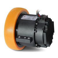
Click menu item Driver->Digital IO Funcons or click the buon. The following window appears.
Funcon and polarity are shown as defaults here.
Figure 3-8 Digital input/output
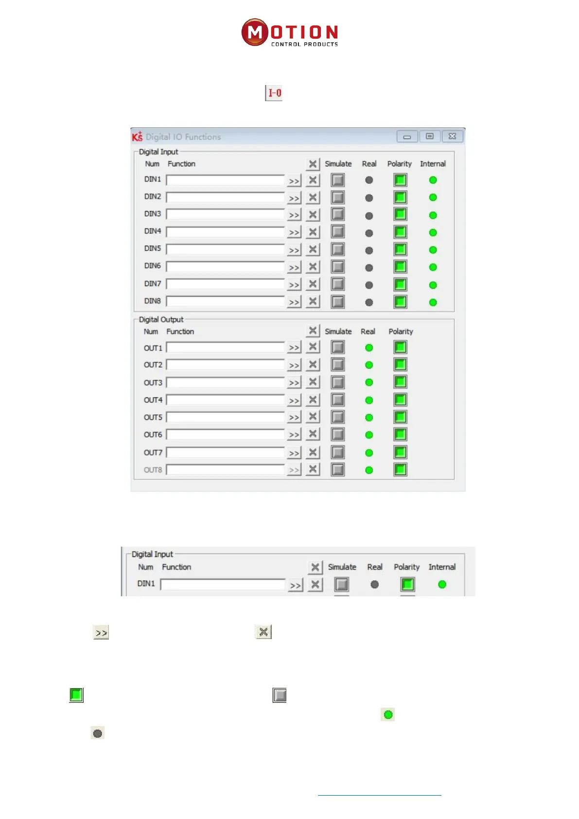
3.6.1 Digital Input
Figure 3-9 Digital input
Funcon: Click to select DIN funcon seng, click to delete the DIN funcon seng.
Simulate: Simulates the digital input acve hardware signal.
Real: Shows the real digital input hardware status.
Polarity: means Internal is set to 1 by “acve” signal. means Internal is set to 1 by “inacve” signal.
Internal: This is the result of Simulate, Real and Polarity via the logic formula;means “acve”, logic status of the selected
funcon is 1; means “inacve”, logic status of the selected funcon is 0.