Moon Control Products Ltd. Tel.: +44 (0)1202 599922 www.mooncontrolproducts.com Page | 23
Chapter4 Performance Tuning
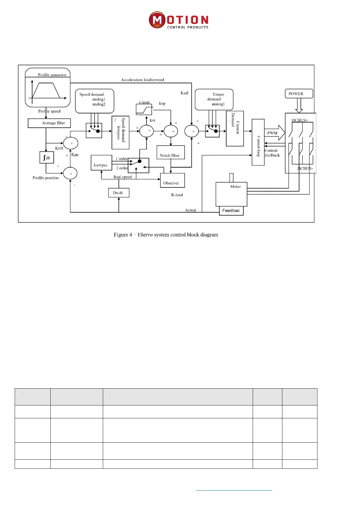
Figure 4.1 is the block diagram of the control structure of the servo system, from which the servo system generally includes
three control loops: current loop, velocity loop and posion loop. For servo systems, good control loop parameters can
improve the performance of servos and beer meet the process requirements of the site. Therefore, it is very necessary to
adjust the parameters of the control loop.
During the debugging process, it is mainly necessary to adjust the velocity loop and posion loop parameters. The velocity
loop parameter is related to the load inera converted to the motor sha by the enre mechanical system. The posion
loop is the outermost control loop of the servo system, which is related to the motor acon mode, that is, the eld
applicaon. The current loop is the innermost control loop in the servo system, and the current loop parameters are related
to the motor parameters. Aer the motor is congured correctly, the system will default the current loop parameters to the
opmal parameters of the equipped motor, so there is no need to adjust them again.
4.1 Tuning Velocity Loop
Table 4–2 List of velocity loop parameters
The me used to adjust the speed control to
compensate for small errors, increasing the integral gain
will result in greater overshoot.