EasyManuals Logo

Motion iWMC Series User Manual

Motion iWMC Series
56 pages
To Next Page IconTo Next Page
To Previous Page IconTo Previous Page
Page #12 background imageLoading...
Page #12 background image
Moon Control Products Ltd. Tel.: +44 (0)1202 599922 www.mooncontrolproducts.com Page | 6
2.2 Interface Denion
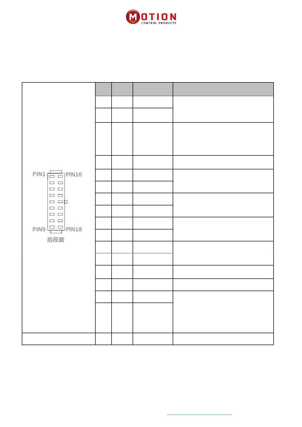
2.2.1 iWMC Integrated servo wheel with Integrated Terminals
Table 2-3 Denion of servo wheel integrated ports
Pin
No.
Name
Colour
Pin Function
1
24V
Red
Positive logic power supply input must be
plugged in. Input voltage: 24V Maximum
input current: 1A Negative logic supply
input
10
GND
Black
11
LOCK-
Blue
The forced release brake input is only used
in emergency situations such as the AGV
battery is dead. It should be noted that the
servo wheel cannot be connected by 48V
power supply when using.
2
LOCK+
Brown
Input voltage: 24V Maximum input circuit:
0.7A
3
CANH
Light green
CAN IN
12
CANL
Light blue
4
CANH
Pink
CAN OUT
13
CANL
White / Black
5
485A
Grey
485 IN
14
485B
White
6
485A
Yellow
485 OUT
15
485B
Green
7
OUT+
Purple
Digital signal output Maximum output
current: 100mA
16
COMO
Orange
Output common
17
DI1
White/ Red
Digital signal input
High level:
Input voltage 12.5VDC - 30VDC
Input current 4-20mA
Low level: 0VDC - VDC
Input frequency: <1KHz
18
DI2
White / Orange
8
COMI
White / Brown
Input common

Table of Contents

Questions and Answers:

Question and Answer IconNeed help?

Do you have a question about the Motion iWMC Series and is the answer not in the manual?

Motion iWMC Series Specifications

General IconGeneral
BrandMotion
ModeliWMC Series
CategoryIndustrial Equipment
LanguageEnglish